Pcomp, Wk 3: Application – Heart Rate Monitor
This week, we finally got to try some basic codes and put our arduino into action! Taking the basic circuits we learned last week, we learned how to have the arduino take input through digital and analog means and then output it digitally using different sensors and voltage regulators.
Honestly, I was feeling pretty good when I came out of class last Thursday. I definitely understood the material, totally got the in-class labs and left with (what I thought) was a solid idea for an application. But oh, how the days pass and other work takes up your time and suddenly you’re like, hmm maybe I’m being a bit over-ambitious. That’s pretty much been my problem the past two weeks with pcomp – coming up with a solid idea for an application. Normally I would consider myself an ideas person but when it comes to pcomp, I’m stumped. Either I feel my ideas are wildly complicated or overly simplistic. After I set aside my initial idea (which, I do still want to try but after we learn how to connect p5), I decided to start real simple and then see if that would work, how I could make it more complex. Thing is, what I thought was “simple” turned out to be way more complex than I could have thought.
It all started out when I was running (because its a great time to think about things) and I remembered that my friend had bought a relatively inexpensive heart rate monitor at Tinkershpere, so I thought – how’s about I hook one of those up to my breadboard and have my digital output be an LED turning on? And if I can get that to happen – maybe I can get multiple LEDs to turn showing different heart rate zones (yes, eerily like what you might see on a cardio machine at the gym…I was running outside and I guess I had a one-track mind (lololol)).
So I bought the sensor and went on Tinkersphere’s website to check out the specs and they had this code listed with it:

“Sweet!” I thought. “This looks simple enough. I’ll take this code and then modify the code from the potentiometer/LED switch that we did in class last week.” So I did that…and the LED just stayed on.
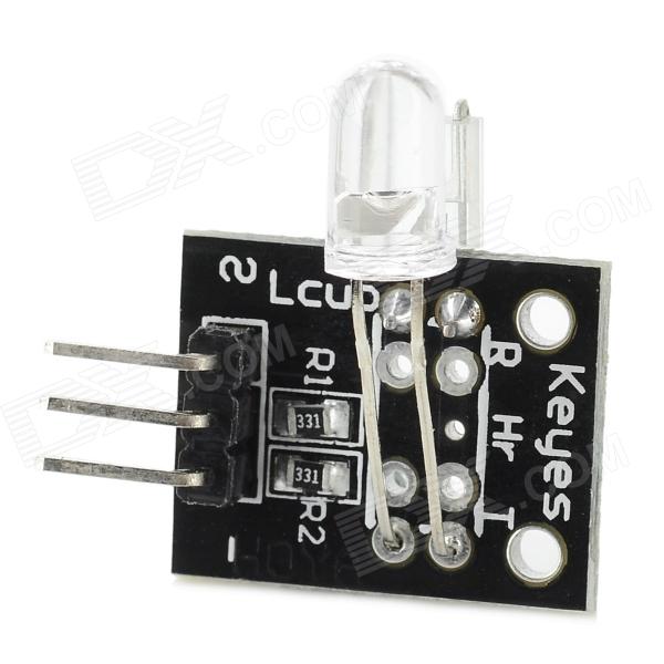
So I decided to do a bit more research on this piece of hardware I got and see what other folks have done with this piece of hardware. This proved to be somewhat difficult, because the identifier that tinkersphere assigned it isn’t used anywhere else. And everytime I searched for “hear rate monitor” I kept getting THIS brand.
So what I decided to do was find my sensor through google images and see what pages it linked to and what information they could give me.
At first, this gave me a lot of eBay sites. But these sites had a slightly different code, so I figured I’d give it a try:
But still, it didn’t feel like anything was happening. From the way the specs read, I thought that a light would turn on when it was hooked up…but…it doesn’t…because I learned that IR stands for INFRARED, and you can’t see it. Unless you’re sitting in the dark with your iPhone. Science!
I asked a couple people on the floor for help, but none of them had worked with this sensor before. Me and second year Sean took a look through the serial and saw that *something* was happening…but most of the numbers hovered close to 1023 (the high point of the range), maybe dipping down to 1017. But even more distressing was that numbers were running even if a finger wasn’t placed in the sensor.
So I started digging more. I looked (DEEP) into the Arduino.cc forums. Again, most of what came up was for that other heart sensor but SOMEWHERE I figured out that my sensor is known as a KY-039 finger heart beat, etc. Once I had a name for this sensor I was more easily able to search the forums and found this spectacular discussion: http://forum.arduino.cc/index.php?topic=209140.15. What I mostly got from reading it is that this is very crappy, temperamental sensor. It does not work very well. Also, the CODE they provide does not do a very good job at interpreting the information. Someone actually went through and annotated the code to try and explain it and mentioned that several pieces of the code are non-functional:
So, people are nice and like to help others, and a few folks posted their tweaks and edits to the base test code and I tried two versions out.
1. A readout that gives lines instead of numbers, plus a blinking LED!
I found a variation of the code that analyzes the peaks in data and assigns it either a (|) or ( |), to visualize the peaks. However, it also showed me that I was still getting readings on the sensor, even if my finger wasn’t there. Reading through the forums, it sounds like ambient light can have an influencing effect. And when I tried this out I was sitting right by the giant windows at ITP.
I played around with the code, installed an LED like how we did in the lab and was able to get it to light up!
But…it was also lighting up when my finger wasn’t in it…which I’m assuming is related to the ambient light. Next step, I’m going to take my stuff home and put it the arduino/breadbox in a box and put the LED on top and see if that takes care of the ambient light problem.
[EDIT: I took it home, put it in a box, turned off the light and still had problems. Actually, the light appeared to blink MORE frequently when my finger wasn’t in the sensor! I guess because it was still picking up ambient light from my computer when my finger wasn’t in the way?2. Other Code:
“Here’s a new version of the code that computes BPM.
The main routine heartbeatDetected() can be converted into a generic library for
that kind of sensor… With my board it works very well now, and the sleep can
be adjusted up to 150ms before the data becomes garbage.If you want to tie the call to the routine to an interrupt handler there is no limitation.
It’s not really needed though and what is needed is to know the latency between calls
(more or less) to adjust the decay of the detection levels.Of course the main loop needs an exact time delta because it prints the BPM. For the
LED blinks however we don’t care too much.I tried 10ms ~150ms with a solid output.
Caveat: If you move the sensor, it may take a while to re-pick up the heart beat.
If that’s an issue for some people I have plenty of ways to fix that I could come up
with, but I wanted to keep this all at a minimal memory footprint…” (sonyhome – http://forum.arduino.cc/index.php?topic=209140.15)
I’ll be honest, I didn’t understand most of the things he said above or most of the stuff in his code. What I can gather is that this code is not as much about making the LED blink as it is about calculating an average heartbeat in BPM (beats per minute). If there’s a significant change, then the program will sense a change in the peak and cause a light to be emitted. But what I really wanted it to do was beat on time with my heartbeat, so unfortunately this code didn’t work for that.
**********
Looking at another arduino.cc forum, one person posted, “I had the same question and it seemed most people said this sensor module just doesn’t work.” >< oof. Learned my lesson on choosing crappy sensors.
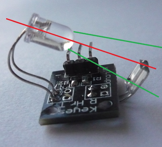
One interesting discussion that came up in the forums was about the relative positions of the two sensors. Simply adjusting them and looking at the serial monitor from the first code, it's clear that changing their positions changes the data. Though what seems to be the most effective placement...is too small to let your finger in?
***************
What I mostly feel frustrated by is my lack of coding knowledge. In my first attempt, I took the (albeit, faulty) data sheet test code and added in the code for the LED from our lab. However, I couldn’t have made all of the modifications to the code that these other folks did. It makes me feel pretty strange that I’m basically copying code (though shout outs to THOSE FOLKS) who wrote it. Is it usually this much of a frankenstein process? Is it simply difficult since I know how to do very few things?
On my way out of ITP today, I vented these frustrations to fellow students and someone said that Rozin said that the way he learned how to code was by using other people’s code and trying to figure out how they did it. So this made me feel better about my process for this assignment. Part of me wishes that I chucked the sensor for another thing, but I do appreciate what I learned about researching hardware, how to use the arduino.cc forums, and try and learn some new kinds of code. But one of these days I would like a functioning project.
*******
Qs – Some of these codes used “period” to define a length of time. How long is a period?
Qs – How do you map out a number (say, heart rate zones) to the 0 – 1023 range? For further application – I’d be interested in figuring out how to hook up three different colored LEDs to show changes in heart rate? Maybe making a wearable? But like, way cooler than a FitBit.
Qs – What is a float exactly? I understand that it relates to decimal numbers in some way. Does it have to do with converting analog data to digital?
Qs – What does it mean to “decay a max” ? Does that have to do with the 0-5V range and conversion from analog to digital?
Qs – What is an “alpha” in this context?