PComp, Wk 6: Serial Input Labs
One thing I really appreciated about doing these labs was how they illuminated small bits of code that we’ve been using since the beginning, but honestly I had no idea what exactly it all meant (re: 9600 bauds, especially). Now I feel (slightly) more confident with writing code, or at least with dealing with the serial monitor.
Lab: Intro to Asynchronous Serial Communication
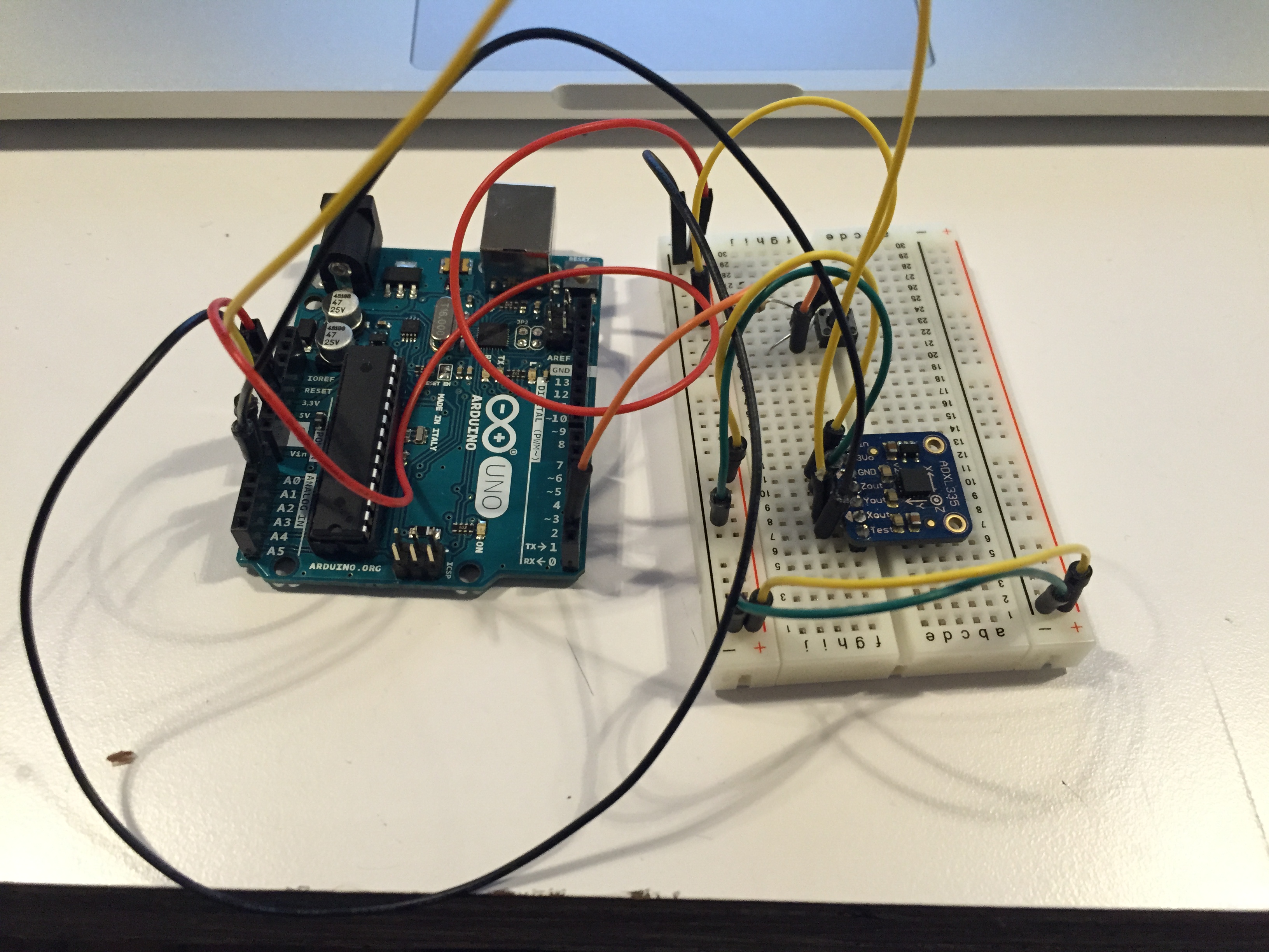
First thought: “Oooo I get to try out an accelerometer!”
No problems with hooking up the circuit. Starting to finally feel like I’ve got a hang on (some of) this stuff.
Now I also get why we didn’t do serialWrite like we did digital or analogWrite for output – get garbage numbers! sends out binary that we can’t interpret.
Alright! Got serial monitor results for all three sensors, and I can distinguish them using punctuation. Cool. Also got the call and response way to work. Feeling good.
Moving on to the second lab…
Lab: Serial Input to the p5.js IDE
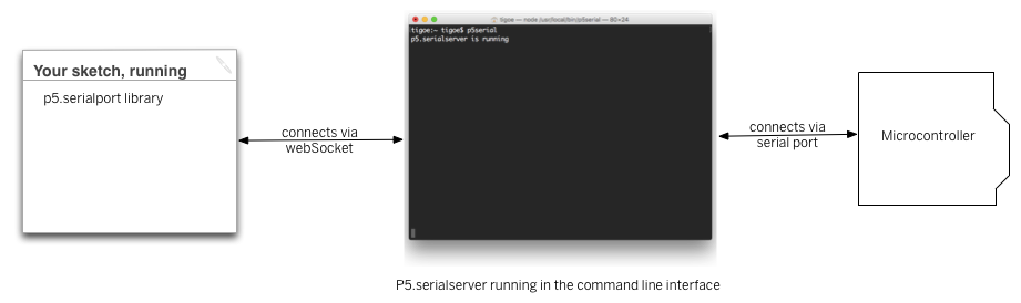
This statement confused me, not sure if it’s a language or concept thing: “The P5.js serialport library can’t access your serial ports directly when a sketch is running in a browser or in the P5 sketch window.”
So, I thought the serialport could communicate when the p5 sketch window was open? Reading further…oh, communicates with server on computer. So it’s just not a “direct” connection? So the sketch isn’t connected to the device, but the code controlling the sketch/IDE is. I think that’s what this drawing means:
When I did my p5 sketch…only got one port? did my USB need to be plugged in? Plug it in…and still only one:
ws://localhost:8081 – which, doesn’t look right to me.
So hopefully that’s mine? copy and pasted the code instead of typing and the same thing happened. So, guess that’s how it goes.
Well, when I started doing the second part of the lab – I got ther error and its also now listening 3 ports, including a USB that must be mine. I switched it and it worked! Or at least, there were no more errors. Not entirely sure why only one port was showing that first time.
At first I could tell that my potentiometer wasn’t talking to p5 (my number wasn’t changing. Did I need to have an arduino sketch uploaded that would read my potentiometer? Oh yes, never uploaded my sketch to the arduino. cool. let’s try that again. YUP. Detective skillz.
Here’s my video of the graphing:
serialCommunication_graph_movie from Zoe Bachman on Vimeo.
Tried out the delay – much choppier, I guess because it’s not gathering data as frequently so there are bigger jumps.
Then I changed it so it would read a string and now there are spaces between the lines. << Not sure I entirely get strings. It’s just a string of bits/bytes? Of different lengths?
Also, why would it read a string that was greater than zero if it said a complete string was every three to six bytes? Shouldn’t it be greater than 3?:
“Remember, the ‘data’ event occurs every time a new byte comes in the serial port. Now that you’re sending an ASCII-encoded string, every potentiometer reading is several bytes long. So you only get a complete string every three to six bytes (three for “0\r\n” and six for “1023\r\n”). Sometimes, when the serialEvent() function calls serial.readStringUntil(‘\r\n’); it gets nothing. That’s when draw() draws the gaps. You need to change your function to check that the resulting string is actually a valid number before you put the string into inData. First, create a local variable to get the string, then check to see if the string’s length is greater than zero. If it is, then put it into inData so that the other functions in the sketch can use the new data. Here’s how you do that:”
Well, got it all to work! yay! I even changed the numbers in the arduino file to get the full 0-1023 range by taking out the mapping. I have to say though, I preferred the sketch when the ranges were 0-255…gave me better control over the graph!