Pcomp, Wk 4: Labs
So I did the servo motor lab again and got it to turn! yay! What I took away from lab is our ability to use Arduino libraries, as well as a growing curiosity about controlling the position of an object. I was so intrigued by the servo motor’s capabilities that I decided to use them in my application (more on that in a different post).
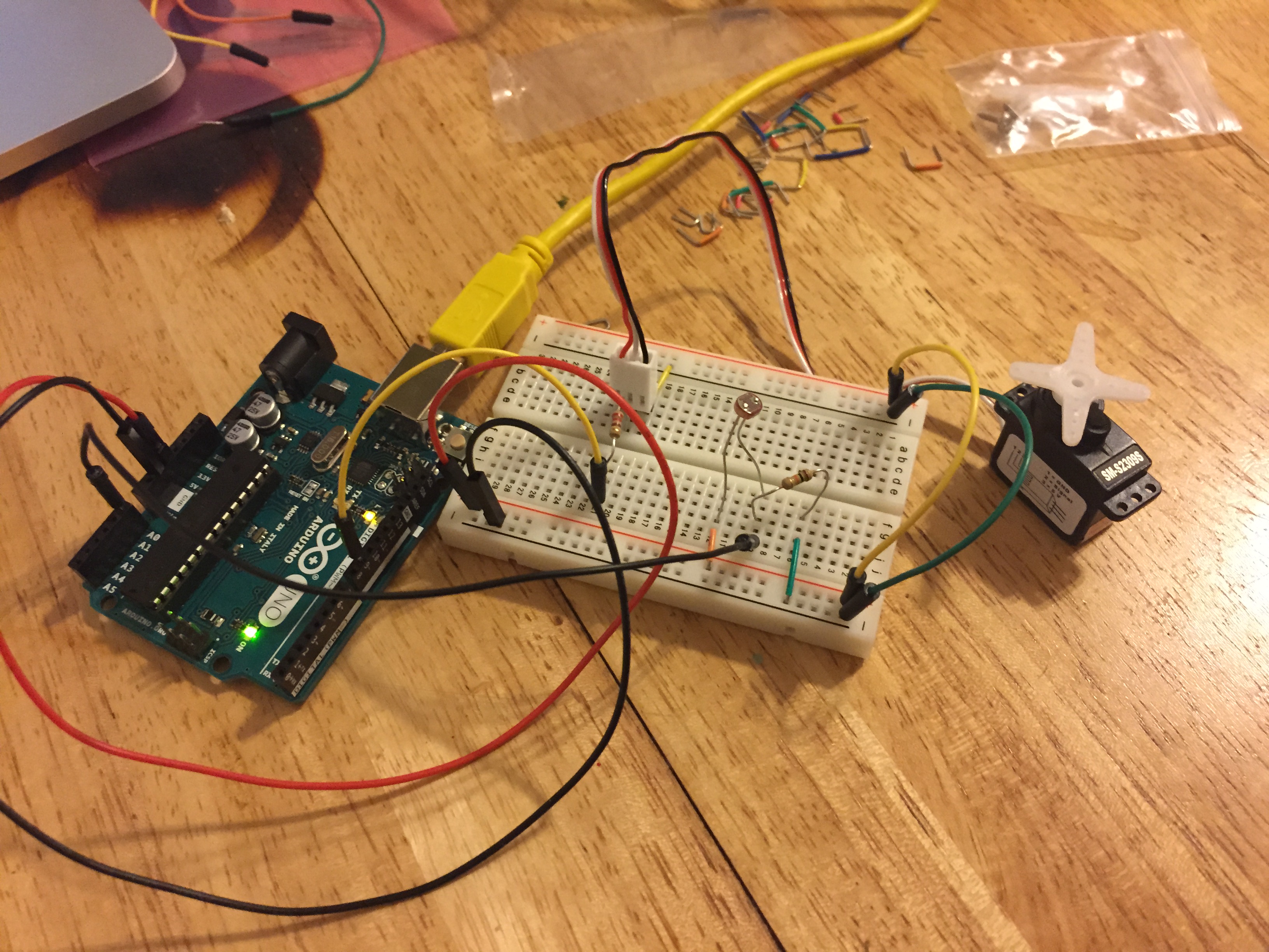
When I began my tone output lab, the first thing I was perplexed by was the readings I got from the two photosensors. I would have figured that if I covered both of them up, then that would give the lowest reading and that if I uncovered them they would give the highest. However, if they were uncovered I got a reading around 640. if I covered the one connected to power, I got readings around 230 and if I covered the one connected to ground I got readings around 900 – is it because they’re working as a sort of voltage divider?
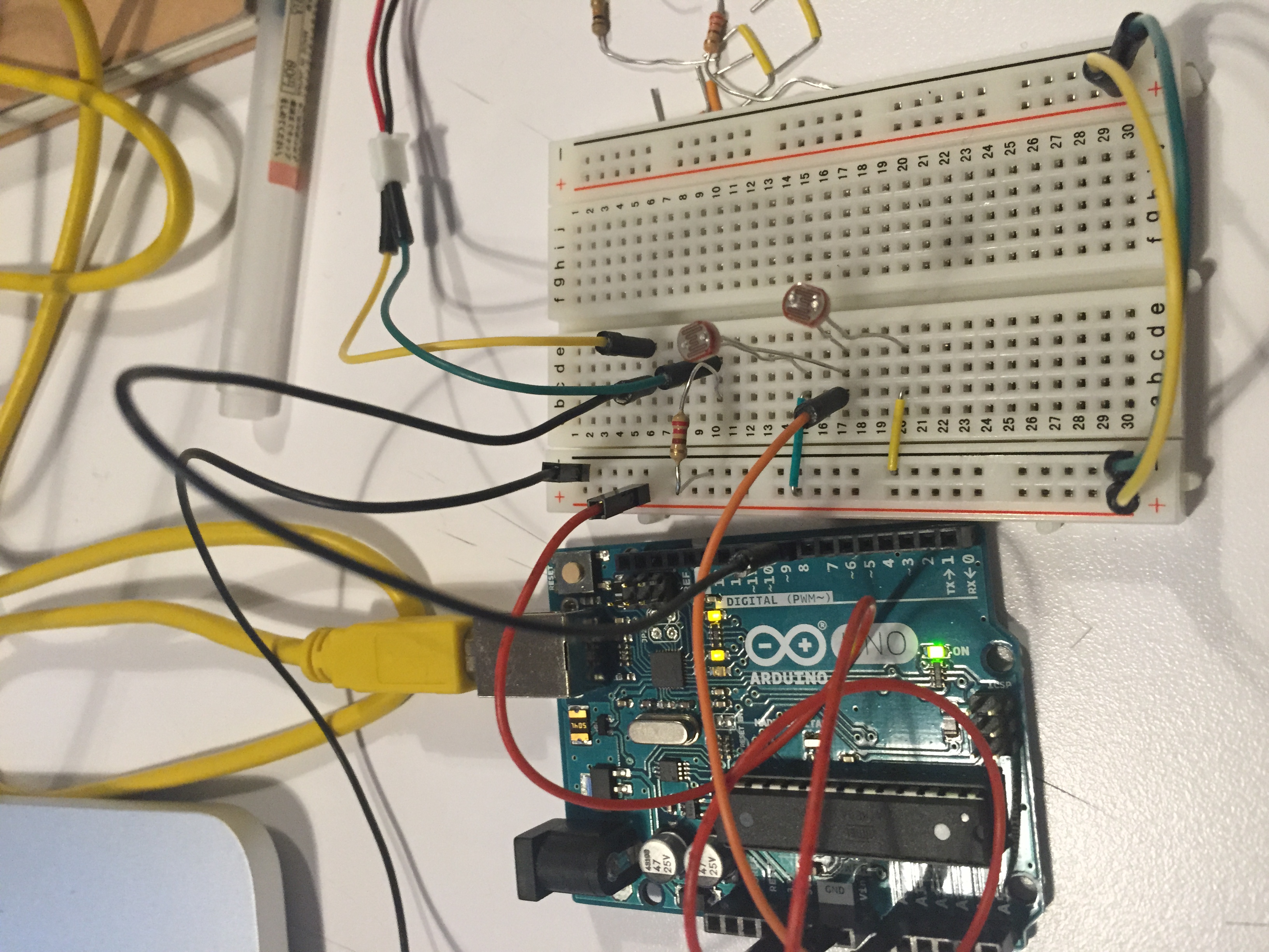
Setup for Tone Output Lab with two photosensors
The sensor readings (obviously) affected the output of the pitch, as well and the volume (or was it the pitch?) mirrored the readings. I checked with Paula’s to see if her’s did the same…and it is. So, in conclusion…I need to understand variable resistors more.
I also tried another photosensor and the same pattern emerged (although with slightly different ranges). So, basically, I just want to know if this supposed to happen this way and why?
Next, I moved on to the melody portion of the lab. This was a good lesson in correctly copying someone else’s code and checking through syntax for errors. Once I figured out my errors, it played the “shave and haircut” melody! Huzzah!
Then I did the last part of the lab with the FSRs. Cool to see that the code uses an array, since we just started to learn about those in ICM. Once I got them to output specific notes, I played around with the different notes assigned to the sensors and made up my own melody!
IMG_4479 from Zoe Bachman on Vimeo.
ICM, Wk 4: Here We Go Again
This week, our assignment was to take a previous drawing and try to use the new object and function formatting to clean it up.
I thought back to my Sol LeWitt drawing from the first week and I wondered how I could transform the individual square (the sketch is comprised of 400 of them) to create an object that can have one of four interiors – either a line is drawn diagonally from bottom left to top right, or diagonally from bottom right to top left, has both lines, or is blank.
I started by conceptually thinking of the code.
The overall square is 200×200, including 400 squares with lines or no lines. I’m thinking I’d write an object that would have variables for the parameter
var square: {
x: 200
y: 100
w: 10
h: 10
(parameters for first square in the upper right hand corner).
and then I’d execute the object in draw() …and add a conditional statement so that it redraws the squares every 10 pixels, until it reaches the edge of the large rectangle, and repeat through the next 19 lines. So, something along the lines of the nested loops that we explored last week.
The next part would be to figure out how to randomize what is drawn in the interior of each of those 400 squares, or have it be blank. Would I use that mysterious array thing I’ve heard about?
I put all of those thoughts in an email to Shiffman. He wrote back and made a few modifications as well as suggesting some hints…
To answer your question, I think what I might start out doing is create an object for an individual cell of the full grid, i.e.
var cell = {
x: 0,
y: 0.
w: 10,
h: 10,
dir: 0
}You could have a variable like “dir” which could have a value of 0 or 1 depending on the line direction. Then you could add a function like:
var cell = {
x: 0,
y: 0.
w: 10,
h: 10,
dir: 0,
display: function() {
rect(this.x,this.y,this.w,this.h);
if (this.dir == 0) {
// line one way
} else {
// line other way
}
}
}Try making this object and then changing dir to false manually and see if it works!
Then you could have dir set randomly:
function setup() {
cell.dir = floor(random(2));
}floor() converts the random decimal number to a whole number so you get only 0 or 1.
Try to see if you can get this to work and then the next step is to make an array of these objects! Which we will discuss in class this week or I can help you with another e-mail or in person.
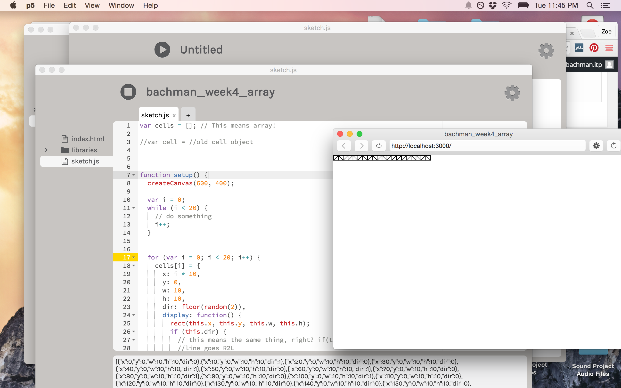
Taking Shiffman’s suggestions, I wrote out the code as suggested, then went in to make the edits. I did some simple math to figure out the relationship between the lines and their corresponding rectangles:
For rect(x, y, w, h) a line that goes from the [bottom right to top left] (R2L) would look like line1(x, y, x + 10, y + 10), and a line that went from the [bottom left to top right](L2R) would look like line2(x + 10, y, x, y + 10).
Then in the draw() function I added a background and wrote cell.dispaly(); and voila! (I’m starting to realize I use this in almost every blog post) – I have a square with a line!
adding this line of code: cell.dir = floor(random(2)) to the setup() function got me a square with a line in it that would change every time!
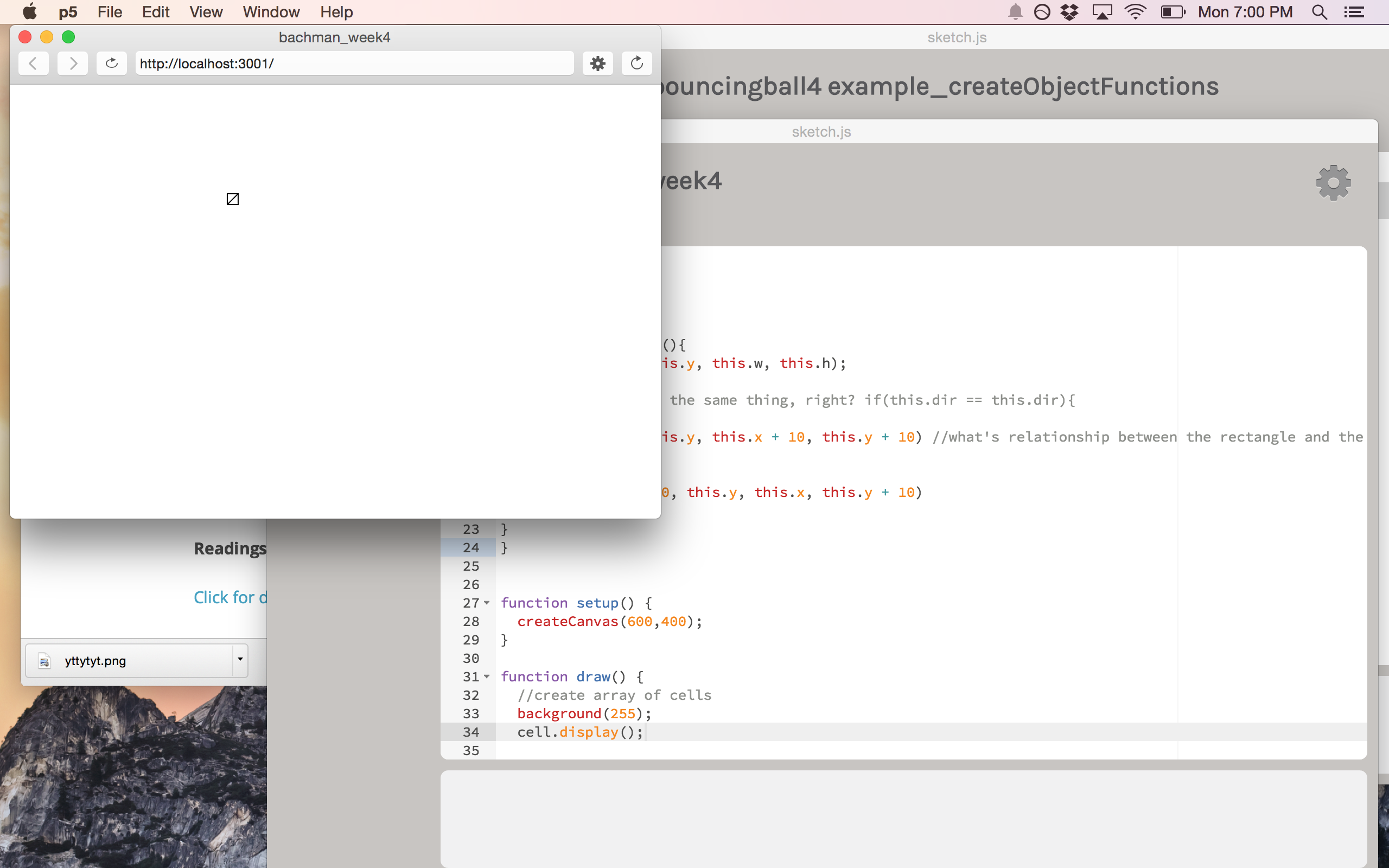
My single square with a randomized line!
********
So now, I wanted my squares/cells in a grid…10 pixels apart, not exceeding 200 in width and height. I went back to the code my partner Xiqiao did last week to look at how he made his grid…I added in his variables and the for loops and got this:
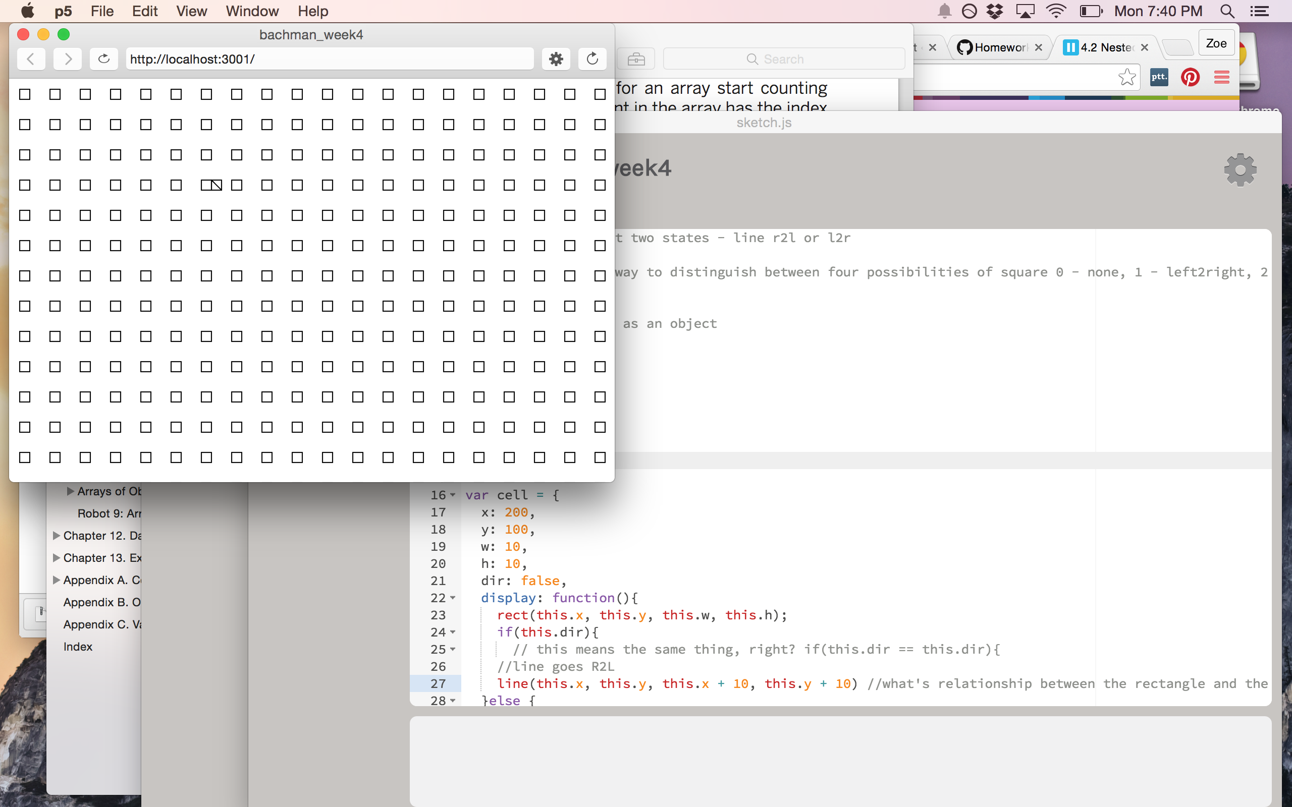
nested loop square grid!
I started to play around with it to try and get it to do what I wanted – basically, have the squares repeat 20 across and 20 down, starting from 200, 100. I don’t want to bore you, but suffice to say I tried out a couple variations on conditional statements and loops. I thought an array might have something to do with it, so I (metaphorically) cracked open Getting Started with p5.js and went to the chapter on arrays…and was pretty lost. I tried adding some code, but wasn’t exactly sure what I was doing.
I also tried to play around with creating constructor functions, which I read about in p5 but we hadn’t gotten into yet. The more I looked at Getting Started, the more I wondered about the best way to create one thing and then get it to repeat in a specific pattern.
**********
Tuesday morning I met with Shiffman to go over the code. He explained arrays more in depth and I finally realized that in order to get the repetition I wanted I would need a variable. We played around with parameters – how many squares, how far apart they would be, etc. We also converted the original cell object into part of an array. We were also now able to add the floor() function to this portion of code, since that information is now in setup() (mostly a note to self: p5 doesn’t recognize floor() if it comes before setup()).
Now with a better understanding of arrays, Shiffman tasked me with trying to get a horizontal and a vertical line of cells – which I was able to do! Separately, that is. They also had been further apart when we tried out the code and I was able to line them up one after the other.
Horizontal line with randomized interior lines
https://gist.github.com/zoebachman/98d408dcffa415903b6b
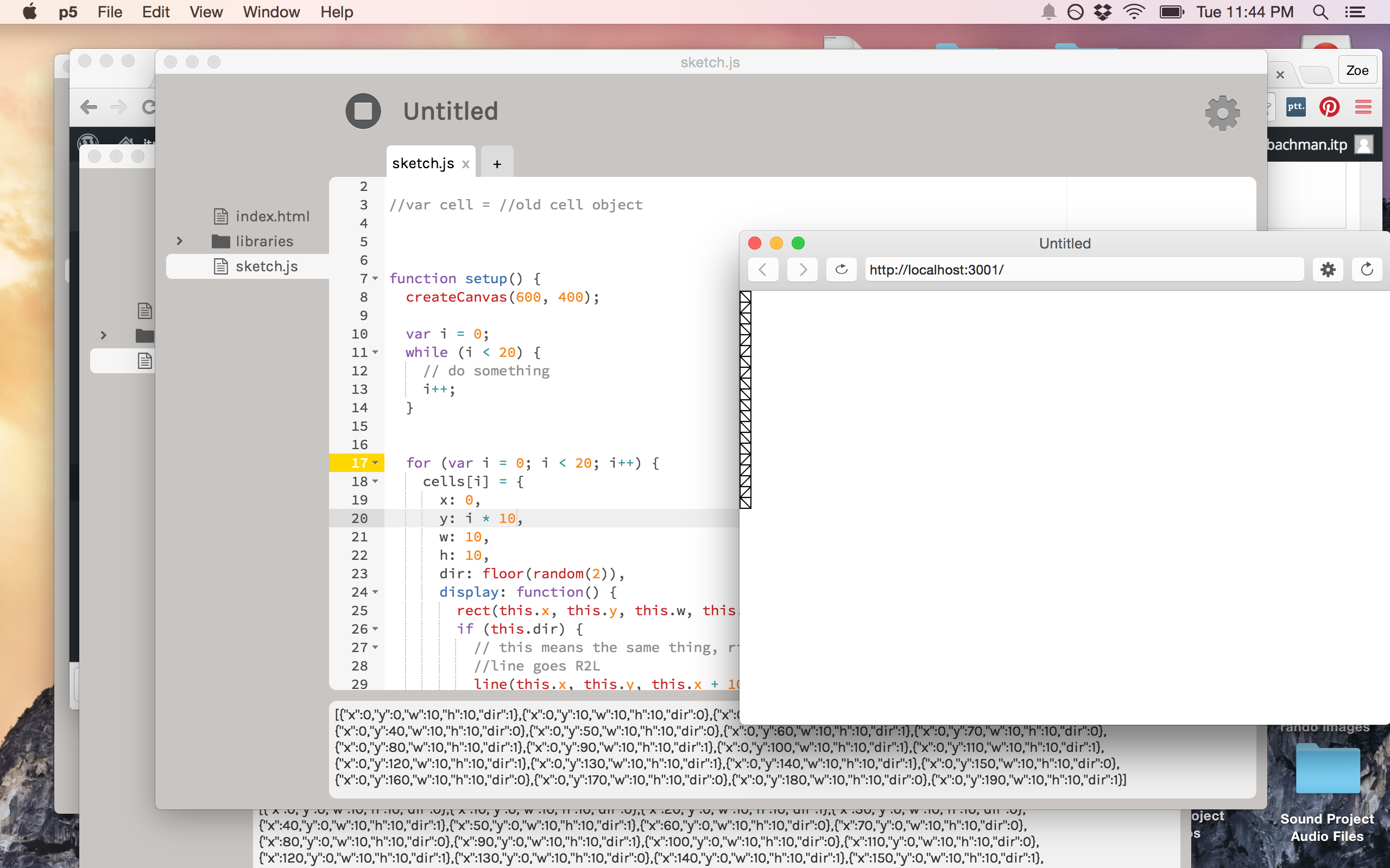
Vertical line with randomized interior lines
I thought I’d try and see what would happen if I had i*10 simultaneously in x and y…This, however, it gave me a diagonal line:
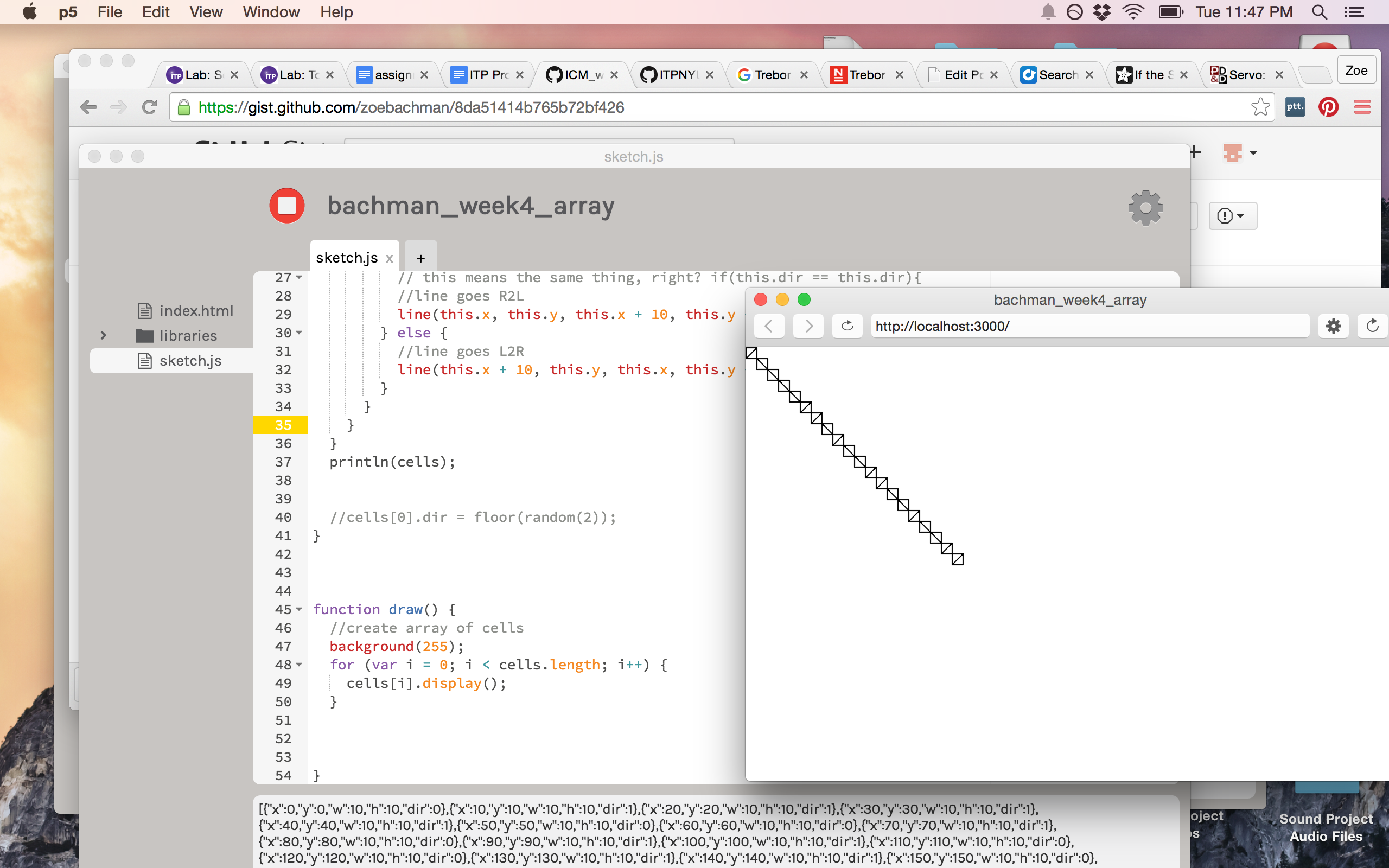
Diagonal line with randomized interior lines. I knew it couldn’t have been that easy.
I attempted to do another conditional statement, but with a new variable (j) and then repeating the array/object block again but switching all the i to j.
I got 30: Uncaught RefrenceError: floor is not defined. Can I not use floor more than once?
It was clear that this additional array/variable did not make for happy code. So, since it’s 11:59, I’ll stop my tinkering and clean up this blog post. The hope is that next week I’ll have a fully functioning sketch!
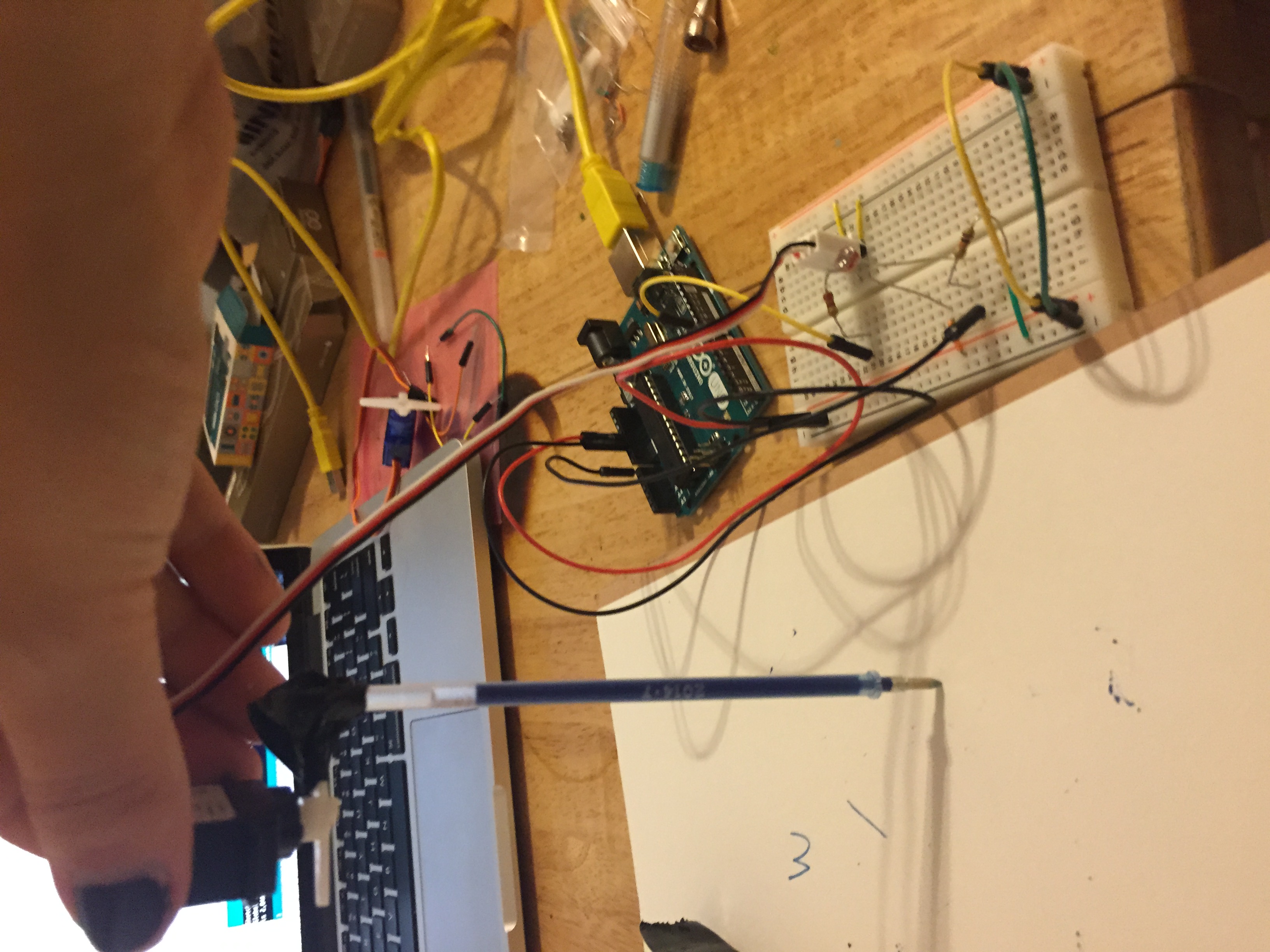
PComp, Wk 4: Simple Application – Drawing Machine
INTRO
As I mentioned in my lab blog post, I was really intrigued by the possibilities of controlling an object’s motion. When I saw the arms of the servo motor rotate, I started thinking about using it to create a kind of drawing machine.
Maybe it’s because a pencil is my favorite tool, but I thought it would be interesting to look at how analog input can translate into a digital context, then be re-written as a different kind of analog output. I like playing with the idea of creating some complicated digital process to do something we could easily do as analog (this has come up a lot in my ICM sketches).
There’s part of me that theoretically/conceptually enjoys the idea of unnecessary over-complications re: digital applications. But I was also thinking about how this particular machine creates a product that you couldn’t replicate by hand- not exactly, at least. (Thought: I wonder if I standardized this enough if I could replicate results, with human interaction being the one variable?)
I used to teach photography to elementary and middle school kids and one of the first things we always did was break down what the work photography means – photo LIGHT and graph DRAW – in Greek. So I thought it would be funny to do a different kind of “light drawing” – using information from the light sensor to power a servo motor that has attached drawing implements.
PROCESS
While I was already familiar with using a photosensor to control a servo motor from the lab this week, at first I encountered some issues that I hadn’t come across before. My servo made a definite hissing sound when I first hooked it up. I tried it out with the second one I just bought and the same thing happened. So, I snooped around the internet and found this page. Looks like it has something to do with the upload. I re-uploaded the sketch and didn’t have anymore weird hissing issues!
Once that was solved, I went about trying to figure out how to attach a drawing tool to the servo motor and what kind of drawing tool to use.
I first tried out a pencil, but I couldn’t get enough pressure to make a mark. Then I thought, what if I found an easy flowing ink pen/marker…maybe one I could take the ink cartridge out of, so it would be thin enough to tape to the arms?
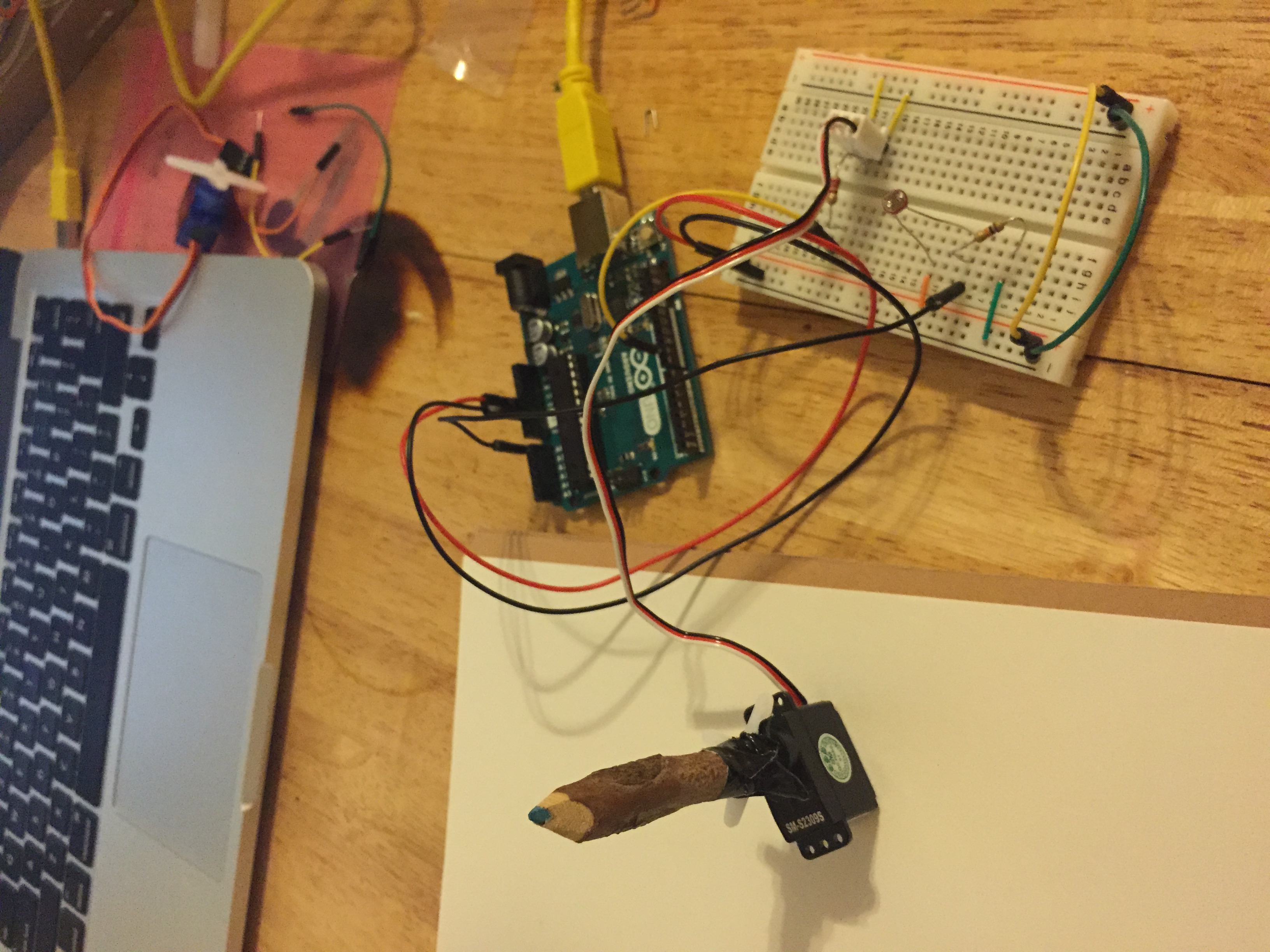
Well…I remembered I had a butt-load of gel pens (because I’m still a 10 year old girl).
I rigged one up, tried out a few different positions and orientations in relation to the motor and settled on the following:
Once I got that to work, I thought I’d try adding a second color and see what I got. Picked orange, bc complimentary colors, yo.
IMG_4467 from Zoe Bachman on Vimeo.
So then I thought…what about TWO SERVO MOTORS! AND FOUR COLORS!
I hooked up both servos to the same analog PMW output pin…
IMG_4473 from Zoe Bachman on Vimeo.
SUCCESS! tricky to do it with two, only because you have to hold one in each hand and have someone wave their hand over the photocell to change the direction. I put my roommate on hand-waving and video duty (hence why it’s filmed vertically…)
THINGS TO THINK ABOUT:
After I got my drawing machine to work, a few modifications came to mind. Currently, it doesn’t function in exactly the state that I want it to. That the pens don’t always produce a mark is the biggest problem. The blue and the orange worked relatively well, but I think I’d try it again with a different drawing utensil.
I’d also be curious at mapping different levels of brightness. Currently, the sensor is sort of working in a switch-ish state that if you cover it up completely or take your hand off forces the motor to turn 180 degrees. Rapidly waving your hand makes a few smaller motions, but I’d like to play around with this relationship more intentionally.
Similar to that, I’d like to see what would happen if each servo motor had it’s own light sensor controlling it’s function so that they didn’t move simultaneously.
Another thing I was thinking of playing around with was using a DC motor and playing with speed rather than position.
Lastly, if I was to develop this into more of a complete prototype…what kind of container/interface would I design for it? I like being able to hold two pens in one hand, and it would need to expand the surface area so it would be easier for the hand to grip while still allowing the motors and pens to rotate. Anyways, just some thoughts…
Project Idea: Social Media Greek Chorus
How does twitter/social media act as a collective greek chorus for current tragedy // sound or video installation that somehow combines tweets into a script //perhaps a live performance?
How do we envision ourselves as the protagonist of our own new Netflix series while in reality we are too afraid to post anything that goes against the community values of our social media and mete out punishment on those who stray? How does our “curation” of our news feeds end up distilling them into a single voice? What does it mean when we become the one who strays?
What is lost when we don’t engage with a plurality of voices? Does a plurality of voices still exist or are we (self)categorizing our analog world into a digital space, only fit to deal with expressions of two types?
Pcomp, Wk 3: Application – Heart Rate Monitor
This week, we finally got to try some basic codes and put our arduino into action! Taking the basic circuits we learned last week, we learned how to have the arduino take input through digital and analog means and then output it digitally using different sensors and voltage regulators.
Honestly, I was feeling pretty good when I came out of class last Thursday. I definitely understood the material, totally got the in-class labs and left with (what I thought) was a solid idea for an application. But oh, how the days pass and other work takes up your time and suddenly you’re like, hmm maybe I’m being a bit over-ambitious. That’s pretty much been my problem the past two weeks with pcomp – coming up with a solid idea for an application. Normally I would consider myself an ideas person but when it comes to pcomp, I’m stumped. Either I feel my ideas are wildly complicated or overly simplistic. After I set aside my initial idea (which, I do still want to try but after we learn how to connect p5), I decided to start real simple and then see if that would work, how I could make it more complex. Thing is, what I thought was “simple” turned out to be way more complex than I could have thought.
It all started out when I was running (because its a great time to think about things) and I remembered that my friend had bought a relatively inexpensive heart rate monitor at Tinkershpere, so I thought – how’s about I hook one of those up to my breadboard and have my digital output be an LED turning on? And if I can get that to happen – maybe I can get multiple LEDs to turn showing different heart rate zones (yes, eerily like what you might see on a cardio machine at the gym…I was running outside and I guess I had a one-track mind (lololol)).
So I bought the sensor and went on Tinkersphere’s website to check out the specs and they had this code listed with it:

“Sweet!” I thought. “This looks simple enough. I’ll take this code and then modify the code from the potentiometer/LED switch that we did in class last week.” So I did that…and the LED just stayed on.
So I decided to do a bit more research on this piece of hardware I got and see what other folks have done with this piece of hardware. This proved to be somewhat difficult, because the identifier that tinkersphere assigned it isn’t used anywhere else. And everytime I searched for “hear rate monitor” I kept getting THIS brand.
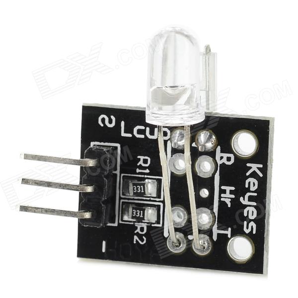
So what I decided to do was find my sensor through google images and see what pages it linked to and what information they could give me.
At first, this gave me a lot of eBay sites. But these sites had a slightly different code, so I figured I’d give it a try:
But still, it didn’t feel like anything was happening. From the way the specs read, I thought that a light would turn on when it was hooked up…but…it doesn’t…because I learned that IR stands for INFRARED, and you can’t see it. Unless you’re sitting in the dark with your iPhone. Science!
I asked a couple people on the floor for help, but none of them had worked with this sensor before. Me and second year Sean took a look through the serial and saw that *something* was happening…but most of the numbers hovered close to 1023 (the high point of the range), maybe dipping down to 1017. But even more distressing was that numbers were running even if a finger wasn’t placed in the sensor.
So I started digging more. I looked (DEEP) into the Arduino.cc forums. Again, most of what came up was for that other heart sensor but SOMEWHERE I figured out that my sensor is known as a KY-039 finger heart beat, etc. Once I had a name for this sensor I was more easily able to search the forums and found this spectacular discussion: http://forum.arduino.cc/index.php?topic=209140.15. What I mostly got from reading it is that this is very crappy, temperamental sensor. It does not work very well. Also, the CODE they provide does not do a very good job at interpreting the information. Someone actually went through and annotated the code to try and explain it and mentioned that several pieces of the code are non-functional:
So, people are nice and like to help others, and a few folks posted their tweaks and edits to the base test code and I tried two versions out.
1. A readout that gives lines instead of numbers, plus a blinking LED!
I found a variation of the code that analyzes the peaks in data and assigns it either a (|) or ( |), to visualize the peaks. However, it also showed me that I was still getting readings on the sensor, even if my finger wasn’t there. Reading through the forums, it sounds like ambient light can have an influencing effect. And when I tried this out I was sitting right by the giant windows at ITP.
I played around with the code, installed an LED like how we did in the lab and was able to get it to light up!
But…it was also lighting up when my finger wasn’t in it…which I’m assuming is related to the ambient light. Next step, I’m going to take my stuff home and put it the arduino/breadbox in a box and put the LED on top and see if that takes care of the ambient light problem.
[EDIT: I took it home, put it in a box, turned off the light and still had problems. Actually, the light appeared to blink MORE frequently when my finger wasn’t in the sensor! I guess because it was still picking up ambient light from my computer when my finger wasn’t in the way?2. Other Code:
“Here’s a new version of the code that computes BPM.
The main routine heartbeatDetected() can be converted into a generic library for
that kind of sensor… With my board it works very well now, and the sleep can
be adjusted up to 150ms before the data becomes garbage.If you want to tie the call to the routine to an interrupt handler there is no limitation.
It’s not really needed though and what is needed is to know the latency between calls
(more or less) to adjust the decay of the detection levels.Of course the main loop needs an exact time delta because it prints the BPM. For the
LED blinks however we don’t care too much.I tried 10ms ~150ms with a solid output.
Caveat: If you move the sensor, it may take a while to re-pick up the heart beat.
If that’s an issue for some people I have plenty of ways to fix that I could come up
with, but I wanted to keep this all at a minimal memory footprint…” (sonyhome – http://forum.arduino.cc/index.php?topic=209140.15)
I’ll be honest, I didn’t understand most of the things he said above or most of the stuff in his code. What I can gather is that this code is not as much about making the LED blink as it is about calculating an average heartbeat in BPM (beats per minute). If there’s a significant change, then the program will sense a change in the peak and cause a light to be emitted. But what I really wanted it to do was beat on time with my heartbeat, so unfortunately this code didn’t work for that.
**********
Looking at another arduino.cc forum, one person posted, “I had the same question and it seemed most people said this sensor module just doesn’t work.” >< oof. Learned my lesson on choosing crappy sensors.
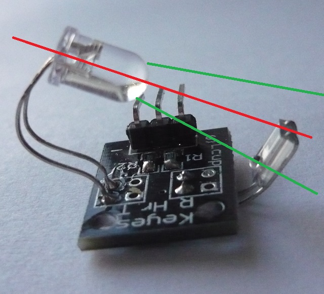
One interesting discussion that came up in the forums was about the relative positions of the two sensors. Simply adjusting them and looking at the serial monitor from the first code, it's clear that changing their positions changes the data. Though what seems to be the most effective placement...is too small to let your finger in?
***************
What I mostly feel frustrated by is my lack of coding knowledge. In my first attempt, I took the (albeit, faulty) data sheet test code and added in the code for the LED from our lab. However, I couldn’t have made all of the modifications to the code that these other folks did. It makes me feel pretty strange that I’m basically copying code (though shout outs to THOSE FOLKS) who wrote it. Is it usually this much of a frankenstein process? Is it simply difficult since I know how to do very few things?
On my way out of ITP today, I vented these frustrations to fellow students and someone said that Rozin said that the way he learned how to code was by using other people’s code and trying to figure out how they did it. So this made me feel better about my process for this assignment. Part of me wishes that I chucked the sensor for another thing, but I do appreciate what I learned about researching hardware, how to use the arduino.cc forums, and try and learn some new kinds of code. But one of these days I would like a functioning project.
*******
Qs – Some of these codes used “period” to define a length of time. How long is a period?
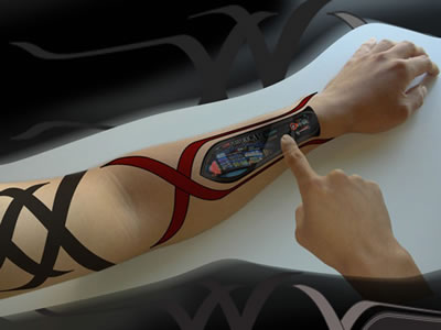
Qs – How do you map out a number (say, heart rate zones) to the 0 – 1023 range? For further application – I’d be interested in figuring out how to hook up three different colored LEDs to show changes in heart rate? Maybe making a wearable? But like, way cooler than a FitBit.
Qs – What is a float exactly? I understand that it relates to decimal numbers in some way. Does it have to do with converting analog data to digital?
Qs – What does it mean to “decay a max” ? Does that have to do with the 0-5V range and conversion from analog to digital?
Qs – What is an “alpha” in this context?
Pcomp, Wk 3: Blog Post – Interactive Technologies
I think…I think I’m still figuring out exactly what interactive technology is.
Like Crawford says, it can exist along a spectrum. You initiate an action, an object responds, etc. So what, exactly, could qualify for this assignment?
Honestly, the first piece of technology that I find myself continually having frustrating interactions with is those credit card machines. You know the ones I’m talking about? They seem to predominate at grocery stores and pharmacies, though I saw one at Blick the other day.

My main point of irritation with this piece of technology is that it is inconsistent. I use a debit/credit card, so when I make purchases I have to specify whether the card should be used as debit or credit. For some reason, even those these machines do the exact same thing, they do it in different ways. So some machines default to debit and then I have to hit a red ‘CANCEL’ button in order to proceed as a credit transaction. However, other designs have you press the green ‘ACCEPT’ button in order to use credit. Still, others have an on-screen option. Sometimes you press that option beforehand and then STILL have to cancel the transaction. Every time I use one of these things it feels like I have to do something different.
Even worse, especially at pharmacies for some reason, there are intermediate screens. do you want to donate $5 to cancer? Oh god, please don’t guilt trip me while I’m trying to buy tampons. I just want my tampons. Also, just an irritant on the way to my anxiety over whether I press red or green on the next screen. I can’t tell you how many conversations I’ve had with cashiers asking which button to press because every time I think I know, I press the wrong one. So I always check from now on, even if they give me weird looks and I always say, “Hey, it’s different at every single place!”
So in Design of Everyday Things, Norman talks about visuals and concepts. How do we conceptualize the step of running a card and changing the type of card? Are we automatically assuming it’s debit and thus have to nullify the transaction? Or is our logic that it must be credit and so we accept it? The colors correspond with whichever choice the machine thinks is most logical in that moment.
Also, those pens that you have to sign with. Why are they always on the left-hand side? Aren’t most people right-handed? And why do they have cradles that never actually fit the pen? I’ve seen so many people struggle to pick one up, awkwardly sign with it and then try, often several times, to replace it in its holder.
Now, this just made me think of new form of payment technology – the Square credit card machines. They’re super nifty, allowing lots of artists and small business owners to now take credit cards as they can be installed on ipads and iphones. They’re very straightforward, even calculating tip options for meals and saving your email so you get an emailed receipt! I do have one gripe – the signature aspect. Have you ever tried to write your signature with your fingertip? Fingertips are not the same size as a pen and whatever sensors they use to pick up those motions distort them dramatically. I, personally, am very fond of my signature but it looks like chicken scratch whenever I use the Square app. I’ve pretty much given up on trying to get it to look like anything at this point.

This person is much more successful at this than I.
I do think these new ways of paying for things are a fascinating example of how we are further de-materializing and abstracting money into something that is more akin to electrical signals than cold hard cash. New apps like Venmo allow you to send money to your friends via an iPhone app (and is also, apparently, easy to hack!). Facebook lets you do the same thing. Of course, there’s now Apple Pay on the iPhone 6 (and you can use it on overpriced groceries at Whole Foods!). A few years back when I was traveling to West Africa, I was really interested in the ways cell phone technology was being appropriated in original ways – one of which was sending money from your phone. Back in Fall 2008 that was deemed totally radical. Funny, how this specific example of the easy of transferring money came right before the stock market crash brought on by those great masters of invisible money down in Wall Street. Being a capitalist society, I’m curious how ways for paying for things will continue to become “easier” and more integrated into ourselves. We’ve gone from cash, to credit cards, to using our phones – how soon will it be that identity and communication technology is stored on or within our person and we can pay for things with the snap of a finger?
ICM, Wk 3: A simple game that turned out to be pretty complicated
I’ll be honest, the last thing I want to do is write a blog post about this week’s assignment. What grief it gave me!
Before I write any more, I want to direct readers to my repository of code:
https://github.com/zoebachman/icm/tree/week3
I created a new file every time I made major changes to the code. So this is the best preservation of all my different attempts. I’ve embedded some aspects of the code, along with a few screenshots/videos. But if you want a real look at the process, go there.
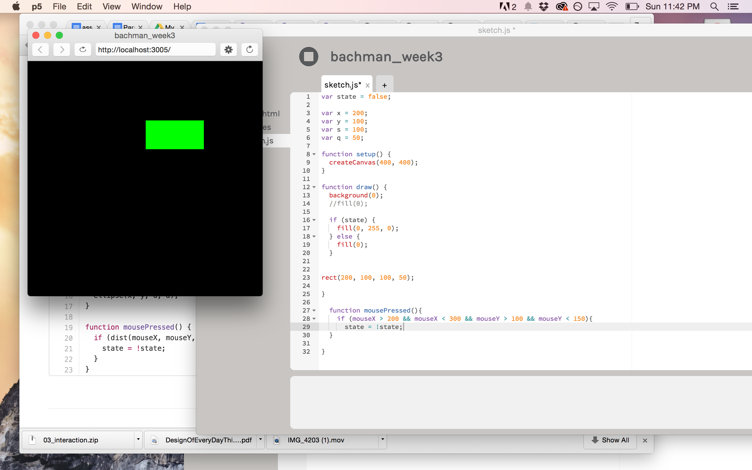
It all started out during class last week when we were learning how to make rollovers and buttons from scratch. As we were playing around with changing backgrounds and fills, I thought, “Wouldn’t it be fun to have the button appear MYSTERIOUSLY OUT OF NO WHERE?” It could be like a sort of game! Maybe I could even had a sound happen when you clicked on the right spot!
I started by modifying the rollover code we learned in class where instead of the background changing color, the fill of the rectangle would change.
At first I had some issues with getting the fill to change and then when I looked at some other code examples, I noticed that the command for rectangle was placed after the if statement. So I tried that and my rollover worked! So I changed it so the rectangle wouldn’t become visible until the mouse was within its parameters and the mouse was clicked.
At this point, the button would only stay on the screen for as long as I you held down the mouse but I really wanted it to remain in that state. So I tried to turn it into a switch using a combination of mouseIsPressed and mousePressed, along with a variable for state so I could use the state = !state codeline.
This…didn’t do anything.
So I set that aside for a second and looked at other button/rollover code examples to see their syntax. I altered my code again, replacing numbers with global variables.
Then, I went back to playing around with this state variable. Commented out the mousePressed function and instead tried to expand the previous if statement by including an else { state = !state. and…it made my rectangle continuously flicker. but go bright when I clicked on it?
Then when I went to correct it, I ended up re-writing a piece of code I wrote earlier…and forgot about. So maybe that had to do with the flickering? Also, why does this stuff make so much sense in class and when watching the videos but when I try to put it into practice I just can’t seem to speak the language? Sad face.
And then…I got rid of the extra code, put back in the mousePressed function and took out the mouseIsPressed command and…voila! I now had the rollover/button/switch of my homework dreams!
I even showed it to my roommate and made her play my little game.
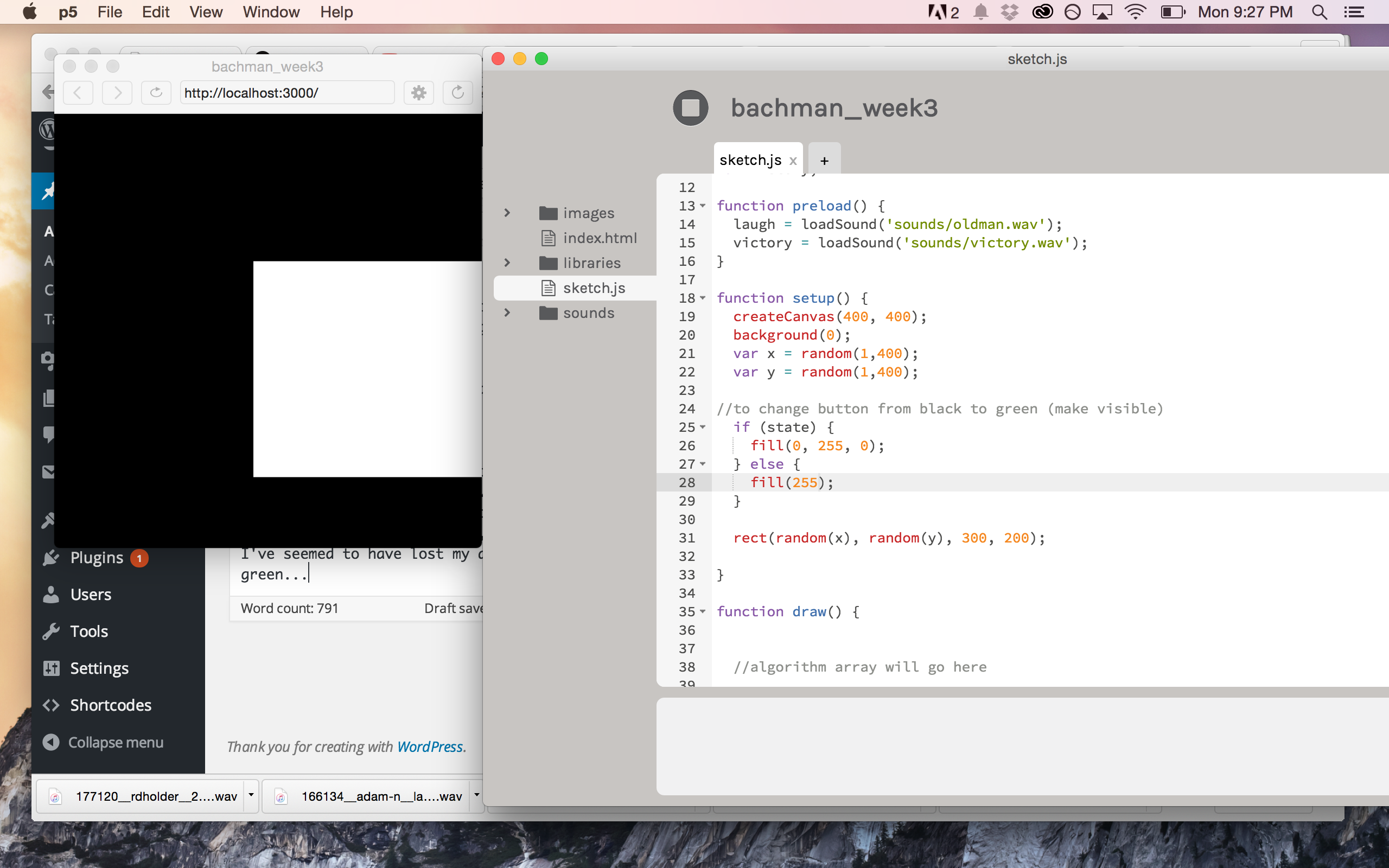
Then I thought, wouldn’t it be fun if I had a triumphant horn play once you clicked on the button?
Apparently freesound.org doesn’t have anything when you search ‘triumphant horn’ but it did have an old man cackle…so I thought it would be funny to have the old man cackle every time you didn’t click on the right spot.
Getting the sounds to play at the right location and time was a bit tricky. I had to make sure the laugh was before my rectangle parameters code (so it would play in the space outside of it) and that my victory sound was after (so it would play inside of it). Using a basic conditional statement proved to be not enough. This was especially true because the laugh was super long, so I didn’t want each mouse click to restart the laugh or else it go pretty obnoxious real fast. I tried a couple of if statements like,
if victory is playing, laugh is not playing, etc. Also tried to use while (while (victory.isPlaying()), etc.) and then p5 froze. lovely. When I got back to it, the while statement made my fill disappear…but it did also stop the sounds after the area had been clicked on (which I wanted). Unfortunately, the laugh was still happening at the same time as the triumphant sound. I was beginning to feel like it was laughing at my anguish.
After several hours, many offers of help and some solid logical deduction, I solved it by turning the rectangle parameters into a local variable and using multiple conditional statements that allowed me to control both the location and duration of the sounds, so they played at the right spot and at the right time:
[One question I’m left with is how to turn off the switch function once the shape appears as well as stop the sounds?] [The other thing I want to try is having an image appear instead of a shape. I found this really fun Bill Nye sound and thought it would be great to have a picture related to that appear.]I was feeling pretty good about my code, but still wanted to do more. Lindsay had the suggestion of having the rectangle appear in a different location each time you refresh the page, so it was more like a game.
Me and the random function are still, unfortunately, not friends. Or maybe we are now, I’m not sure. Something about the syntax and placement of the variables isn’t sticking with me. After playing around with variables and random functions, I put the question to the ICM GoogleGroup to see if anyone out in the ether had some ideas.
I was pleasantly inundated with helpful thoughts, each of which I tried out…with small to moderate success. The advice I got usually did one of two things: enable random rectangles but not have any sound or sound and colors, but no random rectangles. Felt like I was living a conditional statement. If random rectangles, no sounds!, etc.
A lot of it had to do with the placement of certain code – such as the background, fill, and rectangle. Trying to put it in setup seemed to nullify my later mousePressed() function code. Not having it in setup meant my randomization was left to draw and thus looping within the browser.
Sehyun Kim offered a code that used conditional statements and a reset() function. Again, this gave me random rectangles AND the code would reset without having to press the refresh. That was cool. However, it totally messed up my sound code, which super sucked since I spent a LOT of time getting that to work.
I *think* my problem with not having my random rectangles AND my sound work together has to do with my state variable. So I thought, Maybe I need another variable instead of state? Because I changed my state to false for my rectangles because otherwise it wouldn’t fill with a color, but when I did that my sound stopped working correctly.
But when I tried to replace the variable in the mousePressed() function with a different variable name, but also equating to False…it screwed everything up. So, got rid of that. [In hindsight, I wonder if working with a local variable would have changed this?]
So I commented out the sections of code relating to the in-drawing refresh…
and…that got me closer to what I wanted? It starts with a black screen, the laughs happen if I don’t click on the rectangle and when I click on the rectangle – I get a victory sound! Sadly, the in-drawing reset was functioned out, but! If I reset the canvas, the square pops up in a different location. Neat-o! And I figured out how to get the colors to randomize with each reset!
UPDATE: Got my partner Xiqiao’s code! He made a neat sketch featuring an algorithm of lots of flashy squares. When you press the button in the middle, the squares stop flashing.
I integrated his flashy squares and stop event into my button/switch game and voila! Now you have to hunt amongst the squares to find the hidden switch, and once you find it the squares stop blinking and you get the triumphant noise!
I have to say, integrating Xiqiao’s code was surprisingly easy. I just looked for the code that didn’t pertain to the circular switch, added it to mine (modifying a few variables so they didn’t conflict to the one’s that I created) and yeah. It works!
Sound and Vid, Wk 2: Sound Assignment
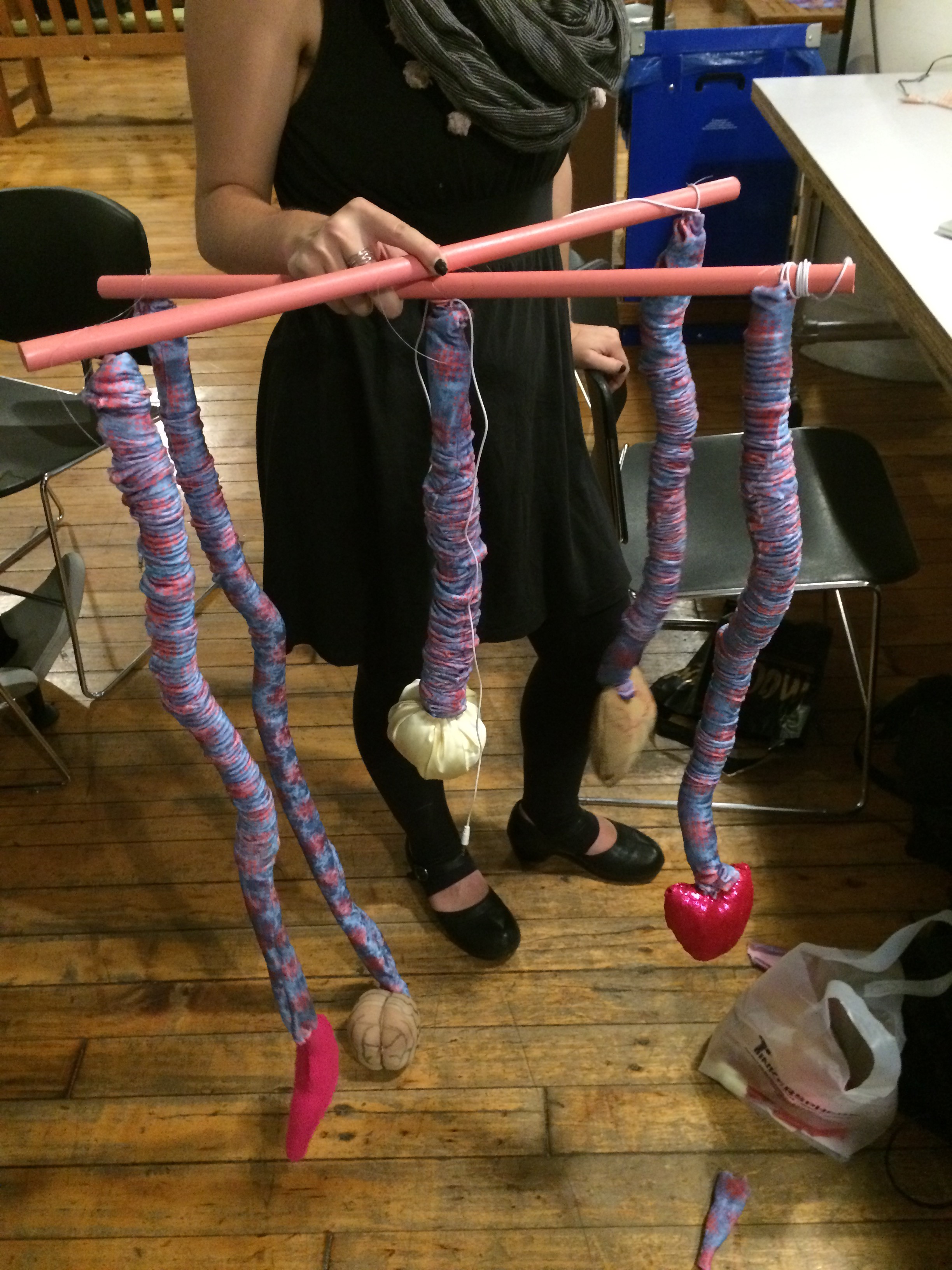
So for our sound assignment, Dana and I went through several ideas before landing on the right fit. We thought about doing recording soon-to-be extinct sounds in New York, either as locations that would one day succumb to rising sea levels or technology that people are phasing out – fax machines, cash registers, etc.
Then we had the thought of recording people’s secrets and creating a sculpture where people could listen to them in a public setting. We went to Washington Square Park and got a few (dare I say) excellent recordings. As another idea, Dana thought: “Sitting on the train thinking. What if we asked people, while recording, tell me the first word that pops into your head? Essentially, recording people’s stream of consciousness. Then we make a giant foam brain that plays blasts the thoughts on a loop . It would be kind of obtrusive and annoying. Again, just musing. Would be easy to get a ton of recordings.” We were a bit worried about getting people to tell us secrets and that what they were telling us wasn’t to form. So I thought we could expand the project and include both ideas – wouldn’t it be interesting to aurally juxtapose those thoughts that are incredibly difficult to say out loud with those that sit right at the tip of your tongue?
We were still interested in creating a sound sculpture, so we then thought of how we could visually represent these differences in expression. I suggested that it was something that had different physical locations corresponding to the different kinds of speech. Dana thought, wouldn’t it be interesting if they were mapped to different parts of the body? We often use bodily metaphors for describing where our feelings, thoughts and expressions come from – “from the heart,” or “gut reaction,” etc. So we drew up a design for a mobile where various organs would hang, each with a speaker that would emit a different audio track corresponding to that specific organ.
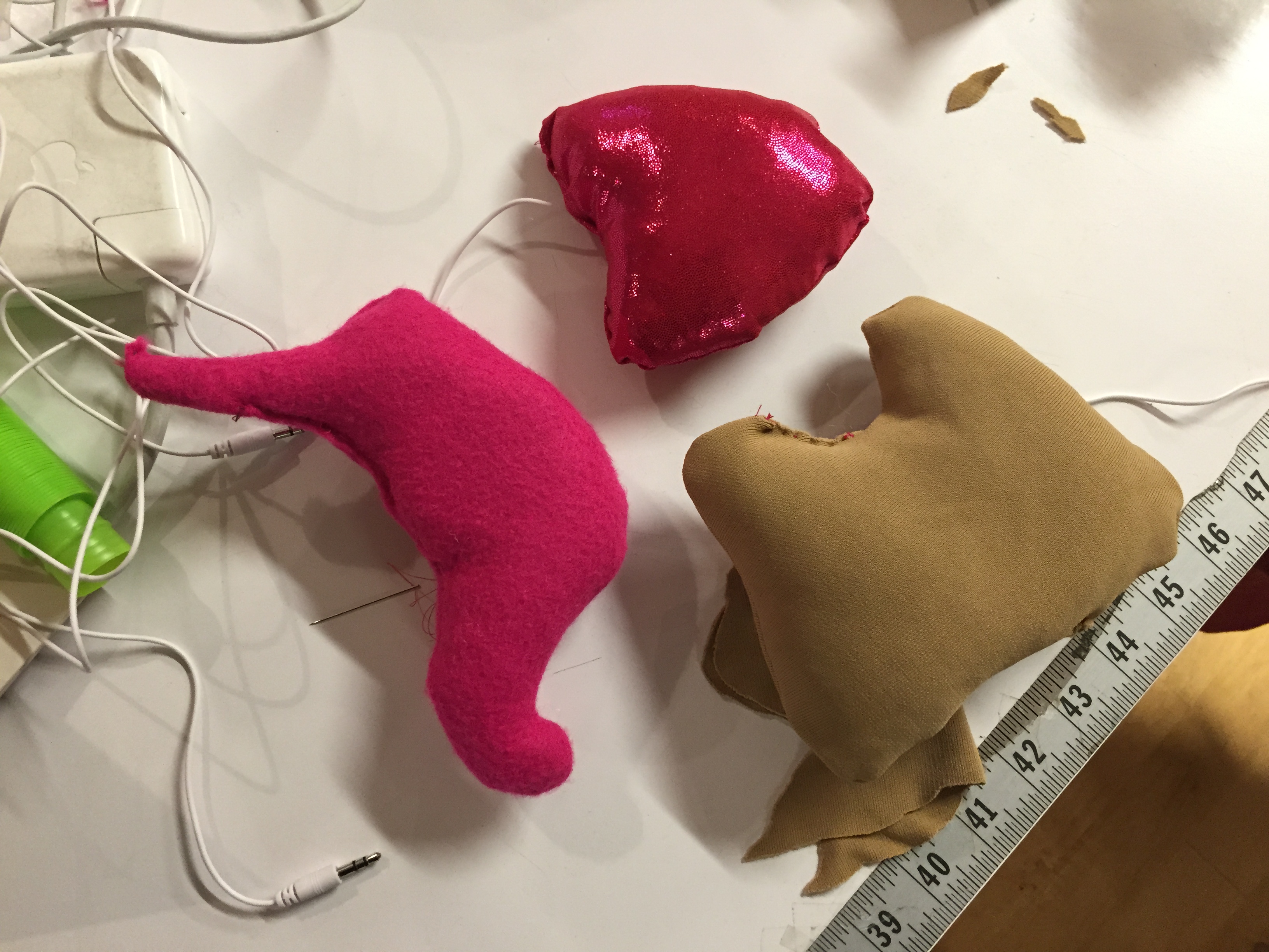
For our organs, we chose the lungs, the heart, the brain, the stomach, and the eyes. Dana found this excellent article that discussed a study that shows how emotions are connected to physiological reactions. So with the responses we recorded, we created tracks that conceptually related to these ideas. The lungs track features secrets relating to fears and anxieties. The heart track is about interpersonal relationships. The brain track showcases the one-word responses, illustrating the idea of what’s at the forefront of one’s mind. The stomach is a series of sounds, the pauses and laughs that were caught amongst speech. Lastly, for the eyes we ended up asking the specific question, “what do you see when you first wake up in the morning?”
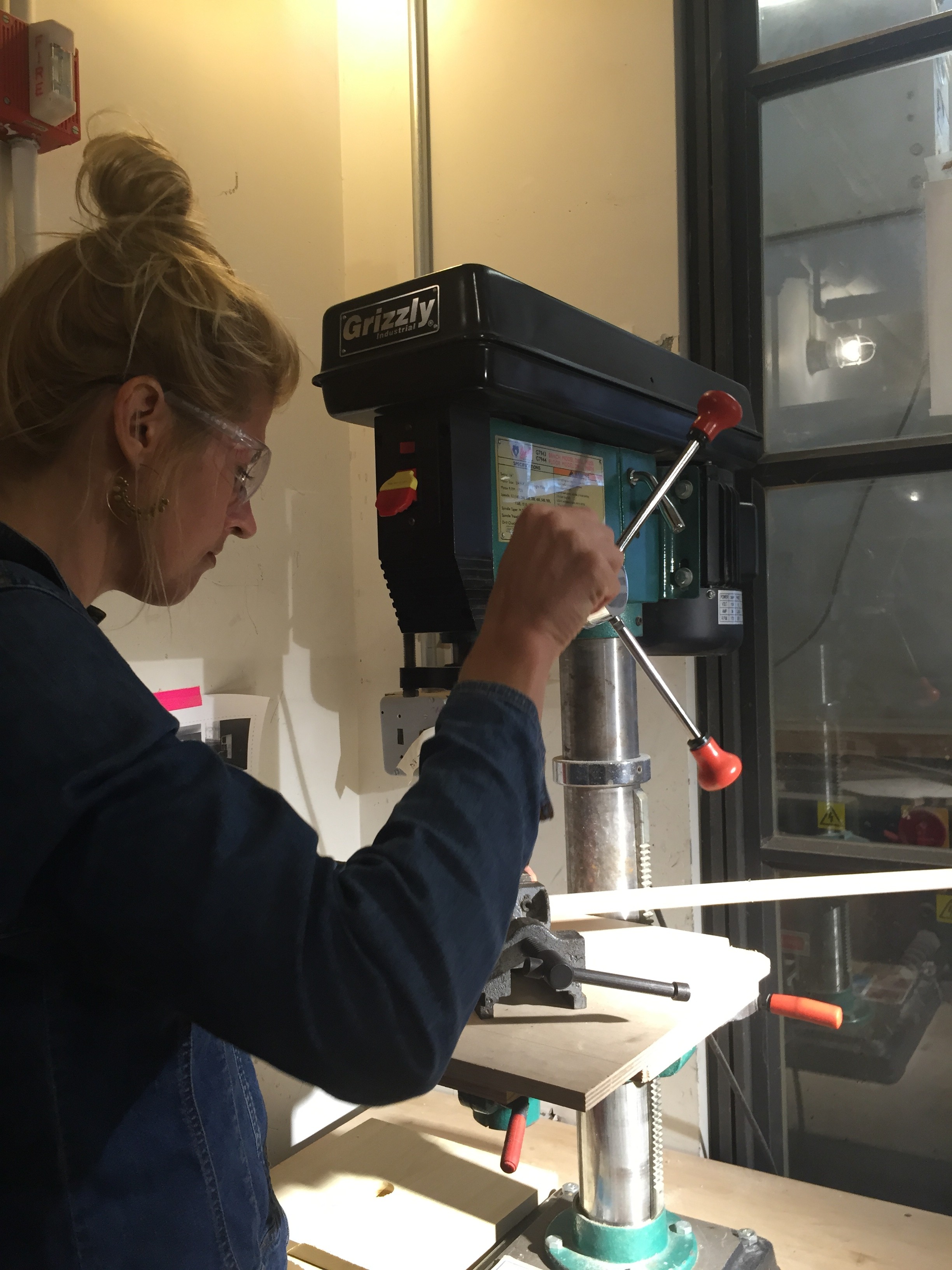
The sculptural aspect let us try out some of the tools in the shop, including an electric saw and drill press, which we used to assemble the crossbar.
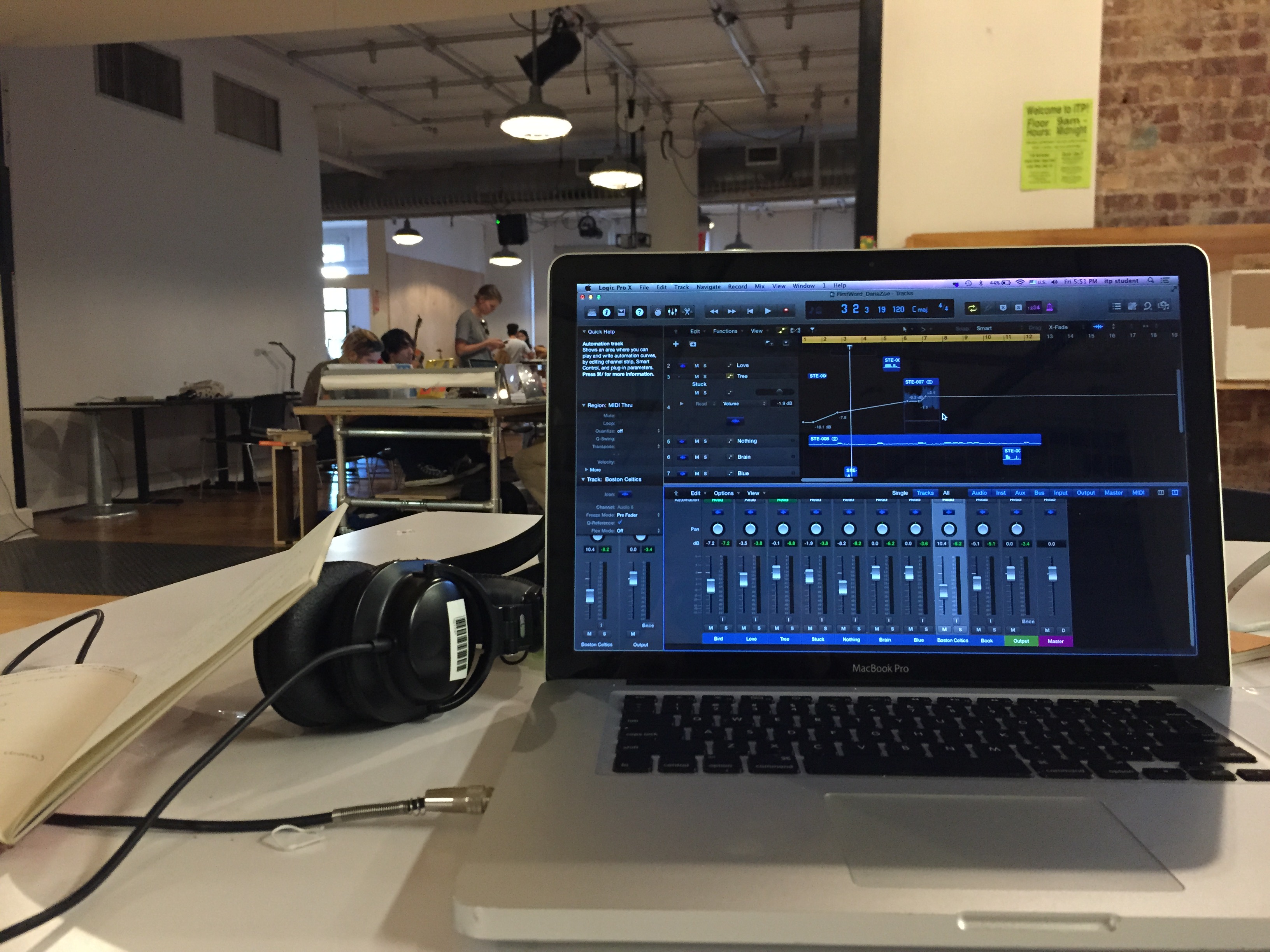
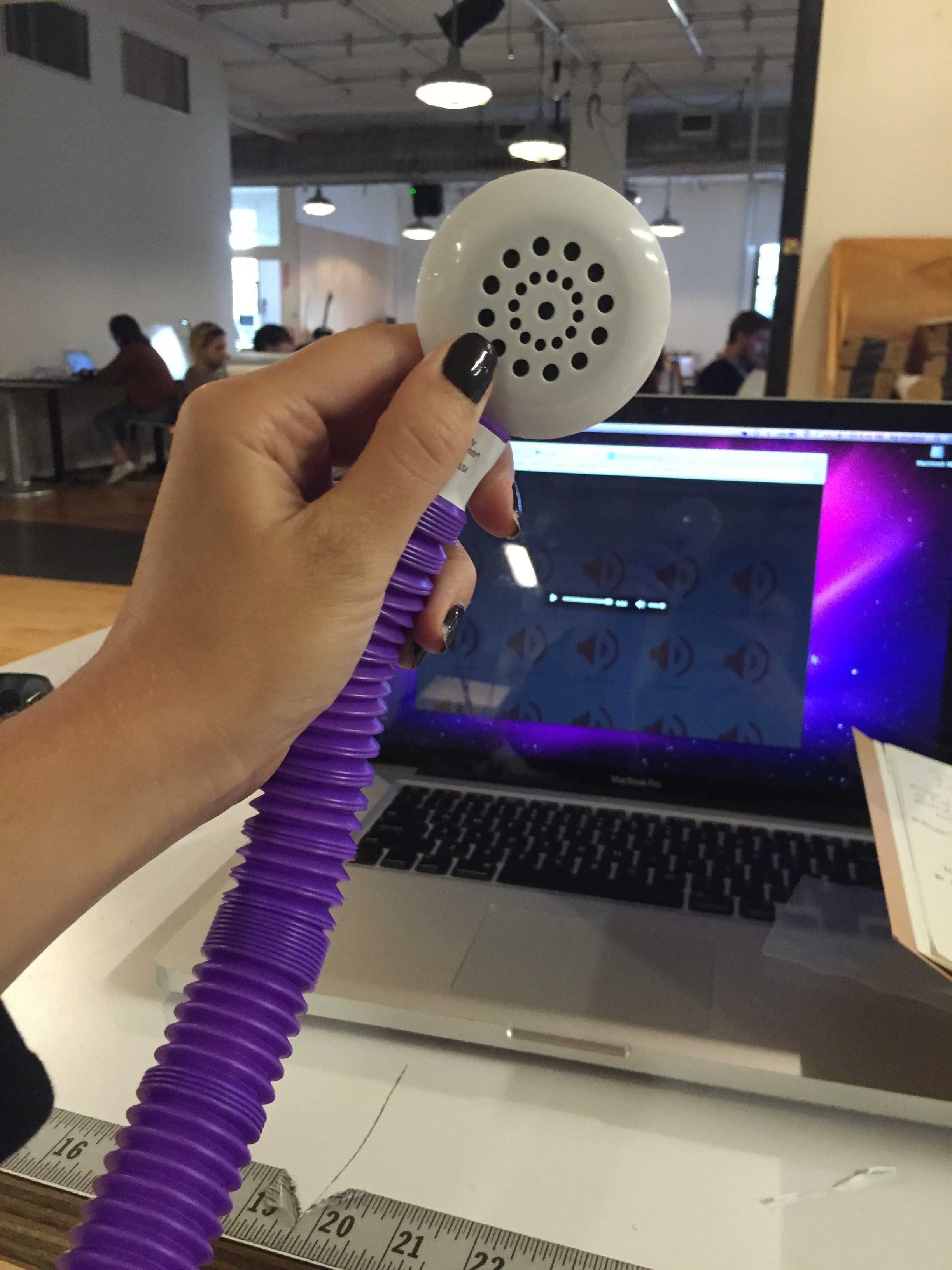
One of our biggest challenges was figuring out how to emit five different tracks simultaneously. After looking at a few different options, we decided to purchase mini-speakers from Tinkersphere and link them to a computer using a Motu audio interface that allows multiple inputs and outputs.
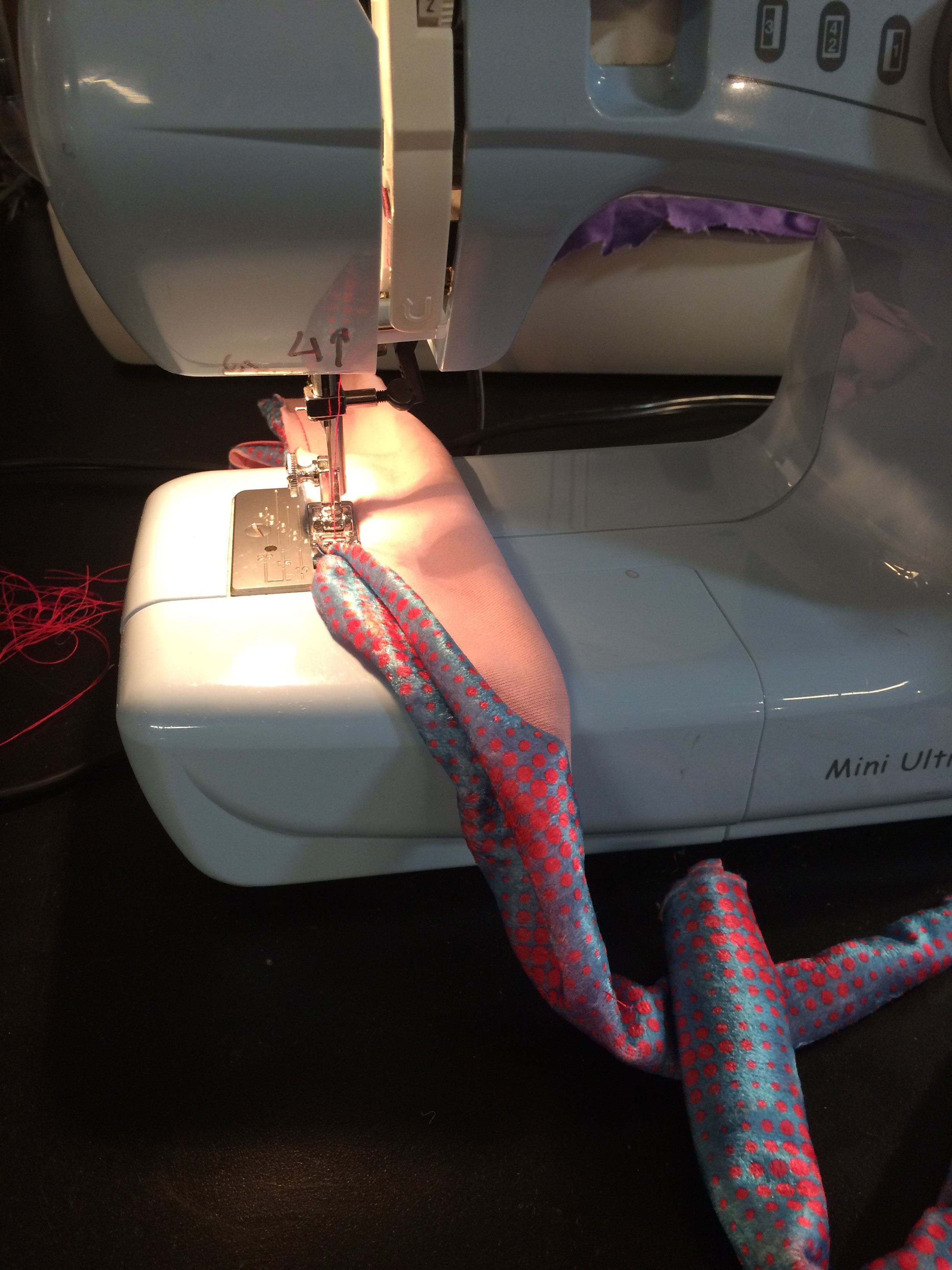
Once we figured that out, we set about assembling our different organs. We purchased scrunchy tubes (that are noise-makers themselves) to attach the organs to the crossbar, which we threaded the speaker wires through.
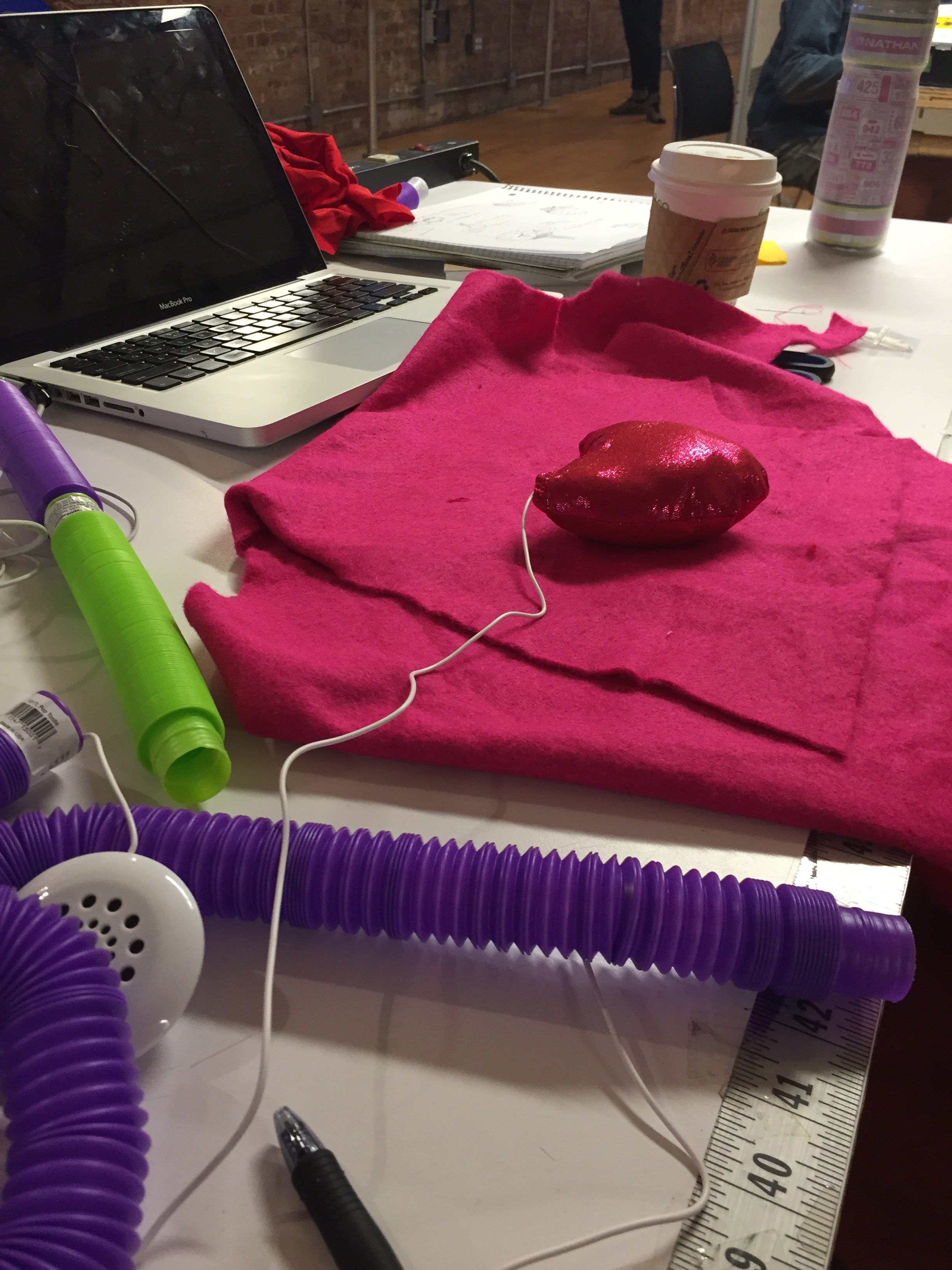
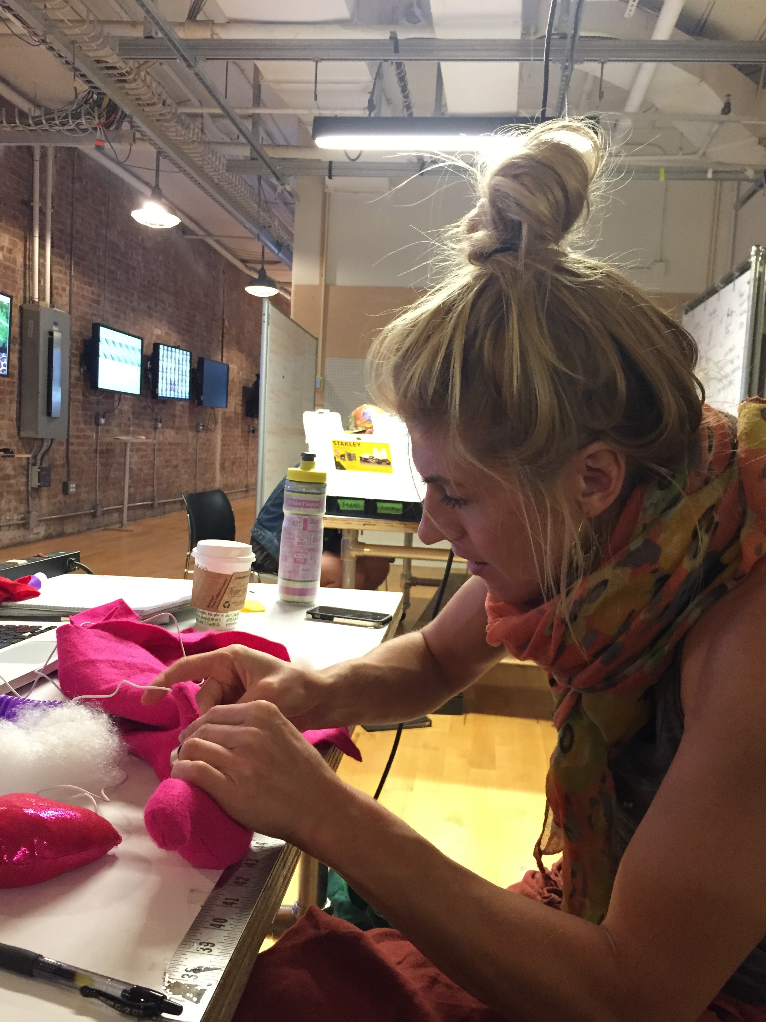
Then Dana, who is a seamstress-extrodinaire, crafted each organ using fabric and stuffing and into which we placed each speaker.
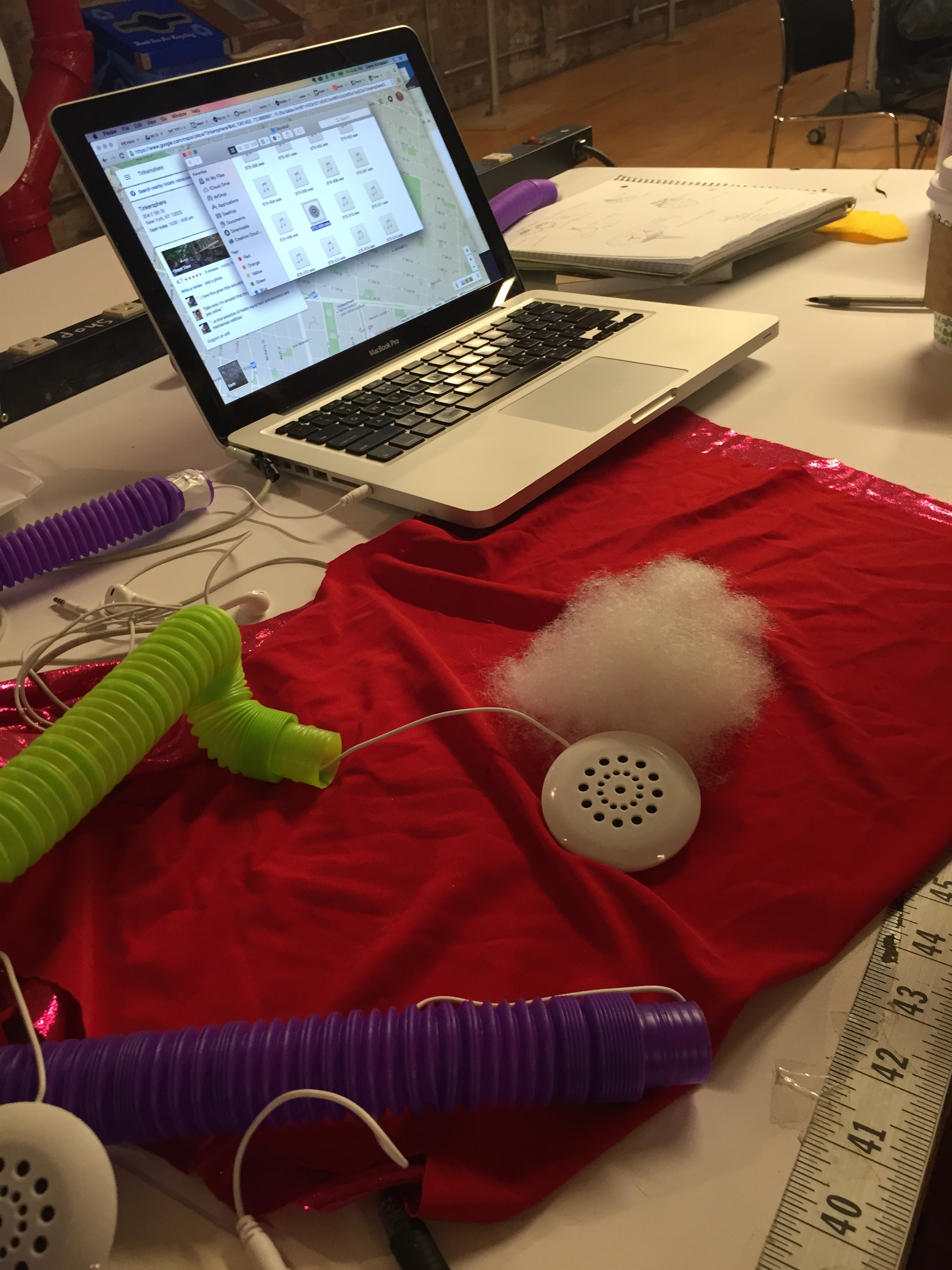
After and awesome trip to MOOD FABRICS (holla, Project Runway!), we got a fun, stretchy velveteen material to wrap our tubes. I wanted a very tactile fabric since the sculpture should invite people to take hold of each tube and bring the fuzzy organs to their ear (yeah, that doesn’t sound weird at all).

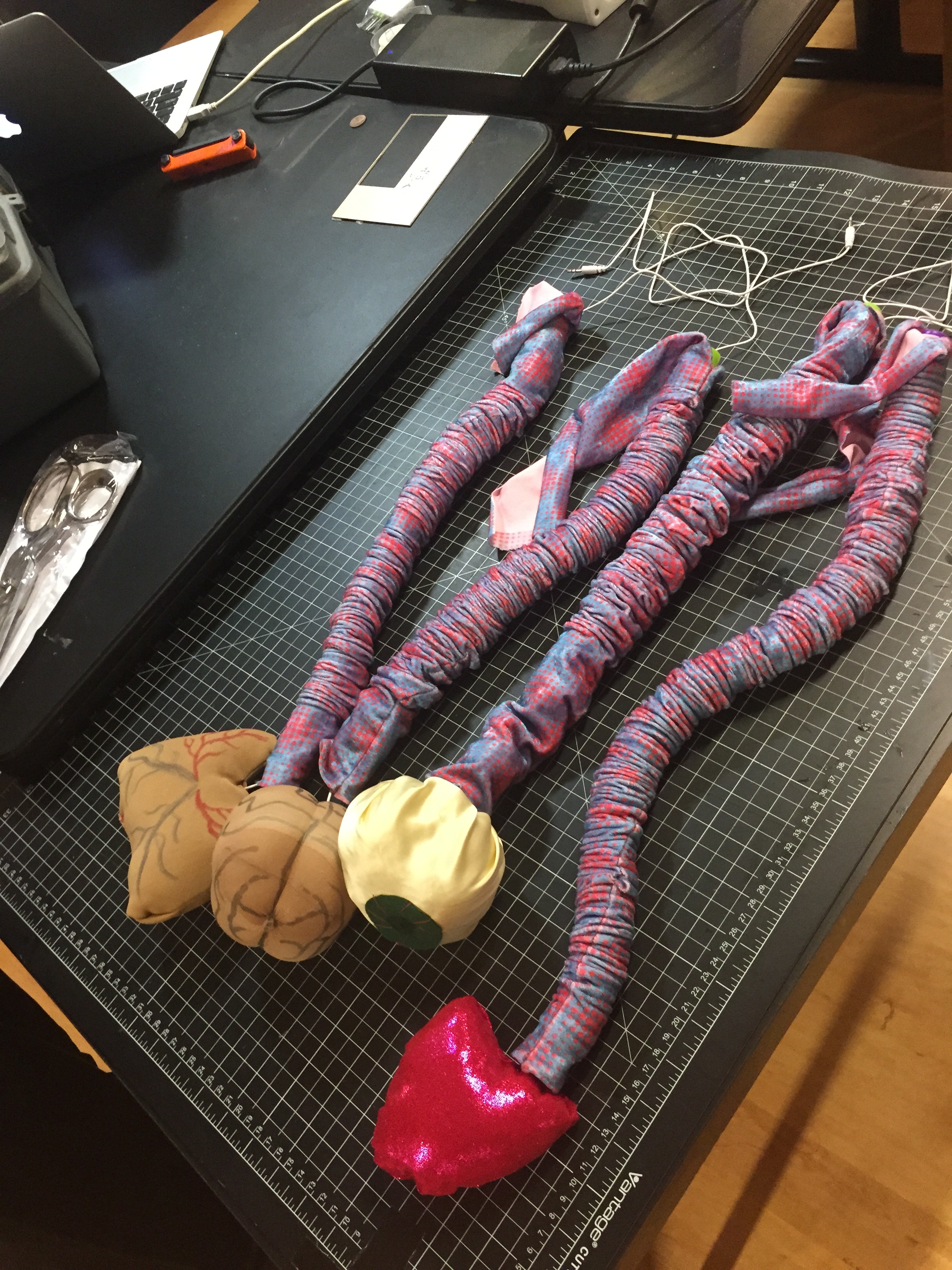
Then we attached our organs to our crossbar and voila! Visceral Voices the sculpture was born.
Now, at the time of writing we have not done a final run through with the Motu because (of course, being our luck)(apparently Mercury is in retrograde…), the internet at ITP went down right when we were trying to install the Motu driver. So tomorrow we plan to come in early to set everything up in full. In the mean time, you can hear the audio tracks here:
Pcomp, Wk 2: Questions for Next Class
- Says that sensors attach to metal pins of a micro-controller, but with arduino we attach sensors to the breadboard – correct?
- Wait, so what I thought was a microcontroller is a development board and they’re not the same? Re: “You can buy and program microcontrollers without a development board or activity board, but you’ll need some extras to do so.”
- What are compilers and linkers?
- Not entirely sure what capacitance is.
- How does a sensor’s range change? Assume dependent on actual environmental information available, but I thought this was something detailed in the data sheet? Does it change between/within a set range of values?
- This sentence just doesn’t make sense to me: “So two, for which you write “2” in base ten, would be “10” in base two, meaning one group of two and 0 ones.” Just converting from decimal to binary in general seems difficult to grasp.
- When a byte rolls over (like in ex: 254 + 4 = 2), does it take up the next byte’s address, like a byte + 2? Or does it just revert to being only 2 of a byte?
PComp, Wk 2: Practical Application – Switch
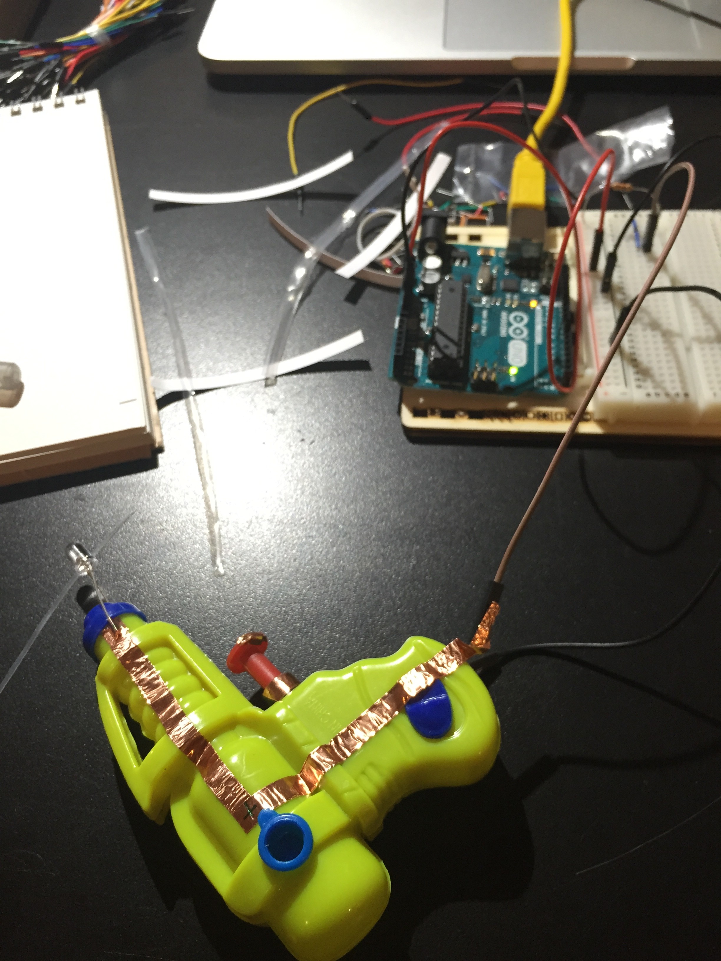
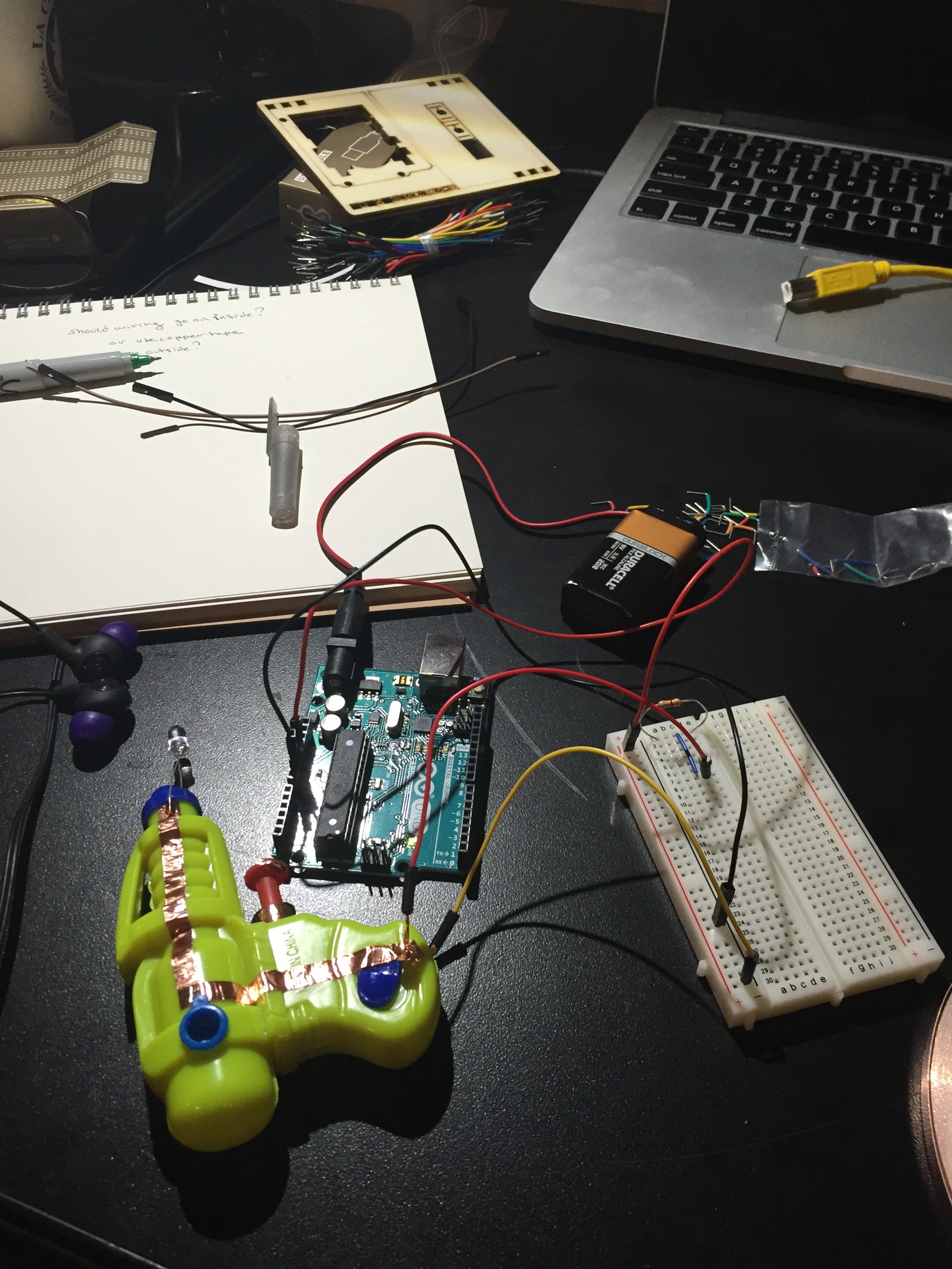
I was really stuck on what to make with a switch. I consider myself an ideas gal but maybe there’s something intimidating that I find about all this or the ideas I did have seemed to silly or impractical or something but I was stuck. So we went to Tinkersphere and Lindsay found this plastic toy gun and was like, what if you made a switch out of this? Bingo.
So I drew a little design:
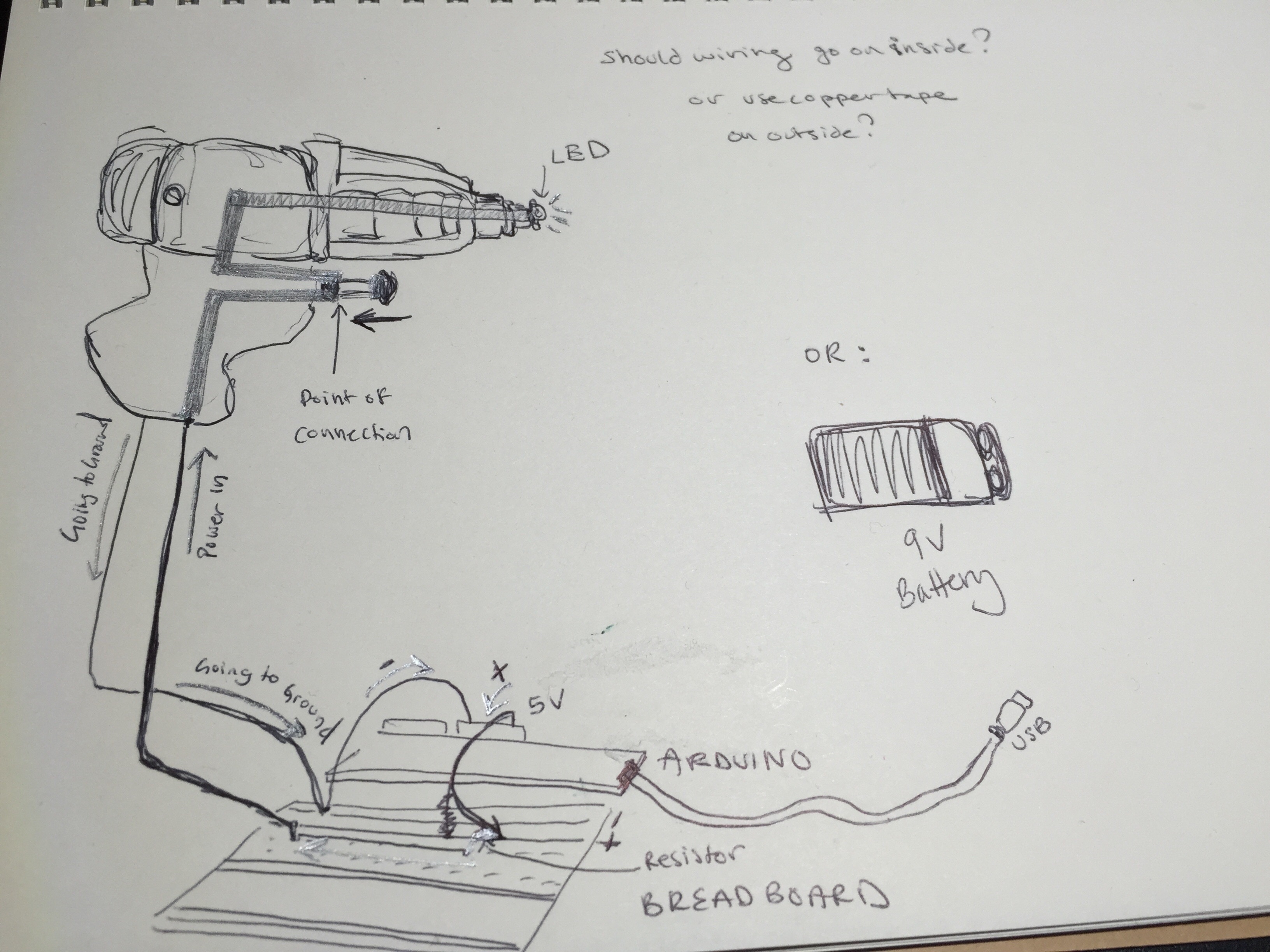
I had bought some copper tape and thought I could use it to create a circuit along the outside of the plastic body, so I wouldn’t have to break the gun apart. The power would run up one side, stop at the base of the trigger, and then on the underside of the button I’d place a little more to create a switch, which would then go back up the side, around to the front and light up and LED, then go back down the other side, through a wire, into the breadboard and to ground.
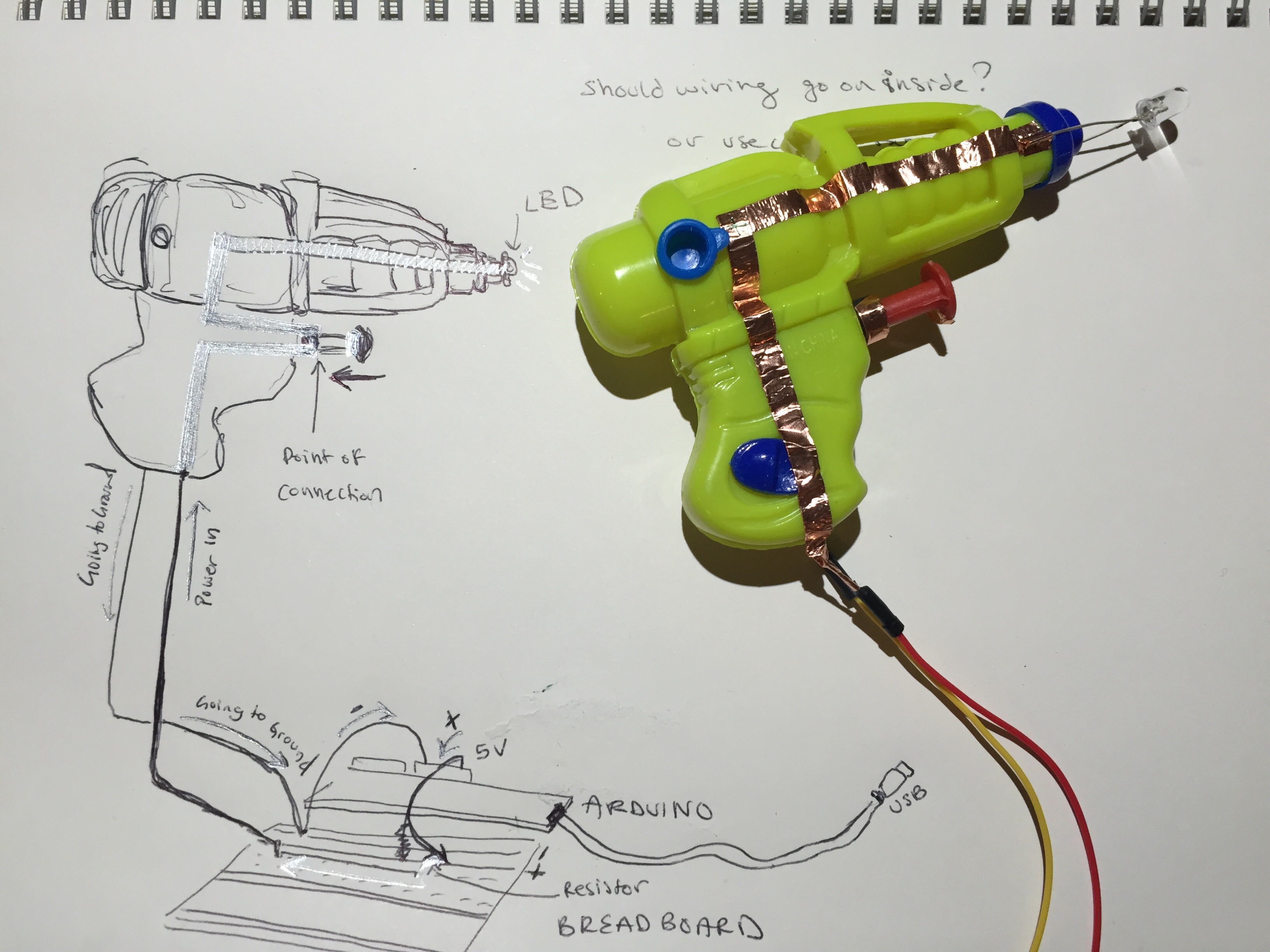
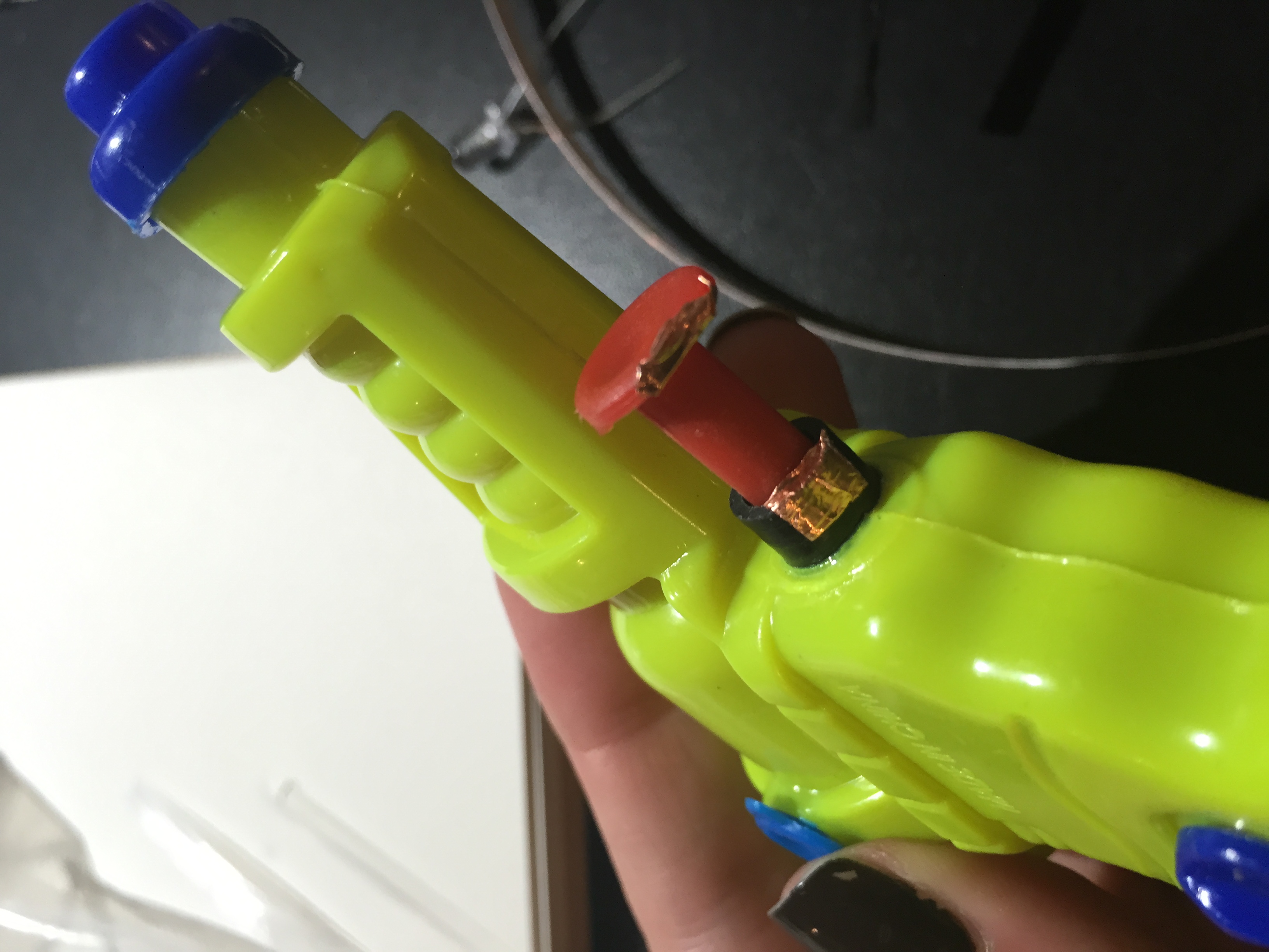
So before I messed around with the switch, i wanted to see if the copper was conducting at all. So I rigged up a circuit and then attached the copper tape to the breadboard using jumper cables. Nothing happened. I tried using a 9V battery instead of an Arduino. Nothing happened. I checked the circuits and while some of the copper wire was working, when it go to the tip of the gun and the LED, it stopped. I got the LED to light using amperage, but when I tried on either side of it no current seemed to be going through.
So then I tried playing around with just the components.
Battery and LED? Good.
Add copper wire? Not good.
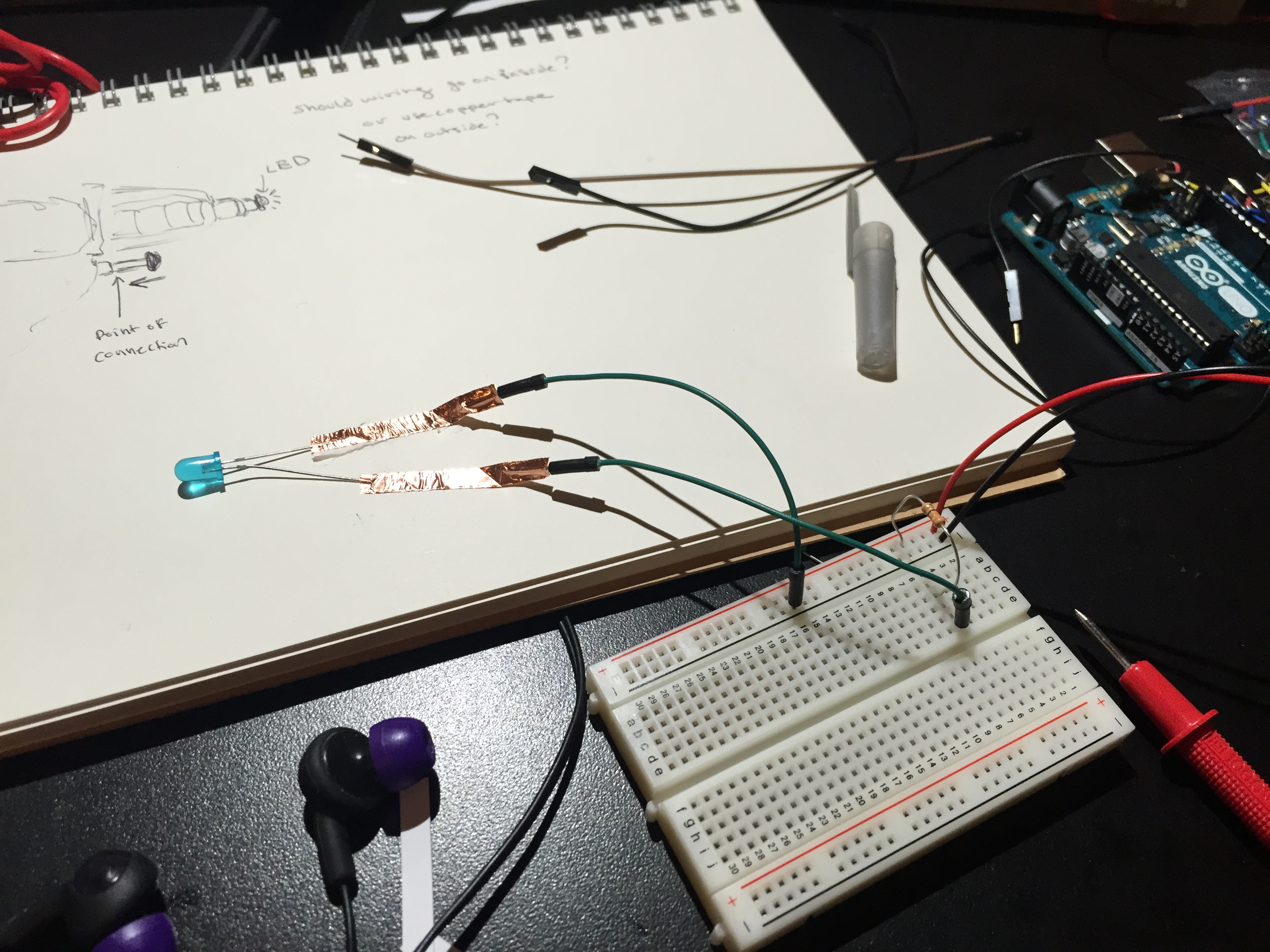
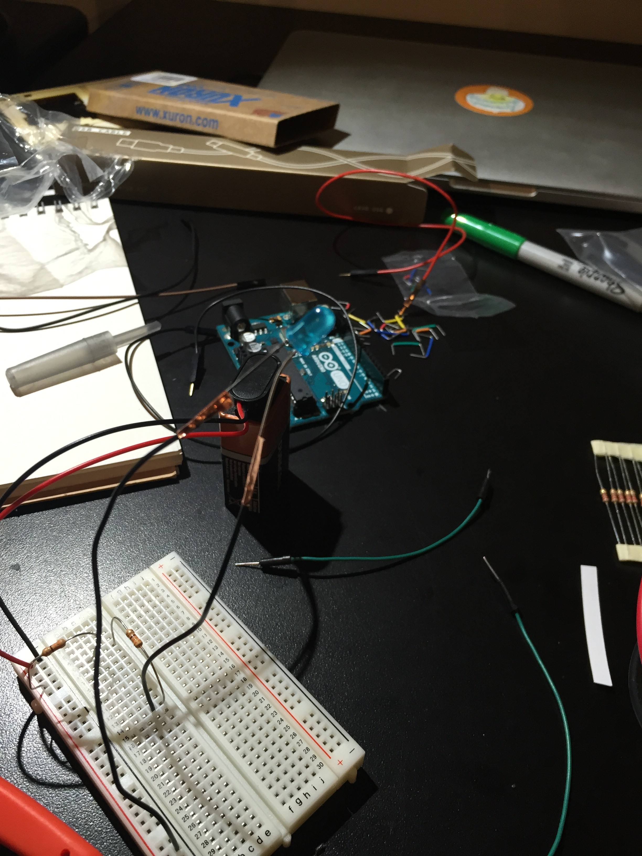
Over and over. Every time I tried to use the wire, the LED would not light. But otherwise, it was fine. So. I’m pretty bummed because I was excited to play around with the copper tape. I still want to try some paper circuits using a 3V and play around with the circuit templates like these. I really like book arts and paper constructions, plus the aesthetic of creating patterns using the copper wire. So. After I finish my readings and reviewing my materials, I play around some more.